Electro Tech is an online community (with over 170,000 members) who enjoy talking about and building electronic circuits, projects and gadgets. To participate you need to register. Registration is free. Click here to register now.
Welcome to our site! Electro Tech is an online community (with over 170,000 members) who enjoy talking about and building electronic circuits, projects and gadgets. To participate you need to register. Registration is free. Click here to register now.
hi every body.
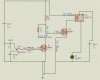
In below circuit why bss89 mosfets breakdown?
at the first, this circuit worked properly,but after 30 minute when I switched power off & on
it didn't worked.
secondary mosfet breaked down.
it never would harmed.
First guess is the 21V at the gate of the second mosfet. Mosfets can usually only handle 20V MAXIMUM before the gate breaks down. 10V is the usual turn on voltage. Usually it's best not to go over 15V.
i should have 24 v , beuase it is needed for special purpose.
pls guide me how can i reduce voltage of second mosfet gate.
where does diode place?
that LED is only indicator for showing that circuit work correctly.
I attached my proteus file for currection.
pls help.
i should have 24 v , beuase it is needed for special purpose.
pls guide me how can i reduce voltage of second mosfet gate.
where does diode place?
that LED is only indicator for showing that circuit work correctly.
I attached my proteus file for currection.
pls help.
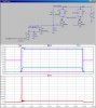
I don't do Proteus. Look at the attached, especially V(g) and V(d2). Note that the input Fet must be a "logic level" Fet because of low gate drive. Your 100K pull-up on the gate of the second FET is way too high, resulting in slow gate switching.
You reduce the voltage by creating a separate power supply. When you are designing circuits, you need to figure out your power requirements first, and make sure you have a power supply for each voltage that is needed.
Don't try to just reduce the voltage, create a new 10V supply for driving the mosfets.
This site uses cookies to help personalise content, tailor your experience and to keep you logged in if you register.
By continuing to use this site, you are consenting to our use of cookies.