Hi there,
I have some questions here to ask. Please refer to the circuit diagram that I have posted.
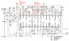
It is a RF circuit for anti theft wireless system. But the problem is the receiver module. Here in the circuit diagram, it shows the connection without the pin number. I have referred to the data sheet and I assumed that the antenna is connected to the FM RF In, ground to GND. But I can’t figure out the other 2 more terminal, which is connected to the transformer.
Besides that, is the transformer X2 used for impedance matching?
And for the receiver, must I use external tuning circuit so that it can be tuned to the transmitter frequency in this case? If yes, then what is the variable capacitor doing there in the transmitter circuit. At first I thought that the transmitter is the one to be tuned.
Thanks in advance for the feedbacks.
I have some questions here to ask. Please refer to the circuit diagram that I have posted.
It is a RF circuit for anti theft wireless system. But the problem is the receiver module. Here in the circuit diagram, it shows the connection without the pin number. I have referred to the data sheet and I assumed that the antenna is connected to the FM RF In, ground to GND. But I can’t figure out the other 2 more terminal, which is connected to the transformer.
Besides that, is the transformer X2 used for impedance matching?
And for the receiver, must I use external tuning circuit so that it can be tuned to the transmitter frequency in this case? If yes, then what is the variable capacitor doing there in the transmitter circuit. At first I thought that the transmitter is the one to be tuned.
Thanks in advance for the feedbacks.