Electro Tech is an online community (with over 170,000 members) who enjoy talking about and building electronic circuits, projects and gadgets. To participate you need to register. Registration is free. Click here to register now.
Welcome to our site! Electro Tech is an online community (with over 170,000 members) who enjoy talking about and building electronic circuits, projects and gadgets. To participate you need to register. Registration is free. Click here to register now.
Hi....
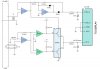
I need your help in this circuit..
It should give the power factor of the load...
I need to calculate the value of T1 and T2 to test the circuit....
-what is the best available simulation software for such a circuit?
Please post a link to the orrigional website with the supporting text.
You need both voltage and current measurements to get the power factor.
Oh, I've just realised that this circuit does that, because it uses silly yanky squiggles for resistors I thought T2 was a resistor and it's not, it's a current transormer. I assume it consists of a number of turns of wire wrapped round one of the mains conductors. The number of turns will depend on the current you want to measure. There should also be a burden resistor which is mising so in this case the output voltage will depend on the input impedance of the 339 which is very high and very variable. I doubt it really matters as the L339 is only acting as a zero crossing detector, I don't know about 100 turns might do.
hi...
thanx for reply...
this circuit is supposed to give the PF of any circuit...
It is my graduation project but i'm facing some obstacles regarding simulation..
I don't want to by the hardware and the circuit fails to operate beside that i'm not sure exactly that operate as PF meter....
I need your help...
any help is highly appreciated
This site uses cookies to help personalise content, tailor your experience and to keep you logged in if you register.
By continuing to use this site, you are consenting to our use of cookies.