hello everyone")
ive decided to build this programmer a while a go and now its done and it dosent work ! , **broken link removed** a tait variant parallel port programmer, all tests specified on the website was done successfully but i cant program a F84A or the F628A it writes the code and
gives me a "verify failed at address 000h !" error then when i close icprog and open it again to read the pic its blank and full of 0x3FFF
so i thought to myself that the things ive done must cause it not to work so heres what ive changed
* swapped the 7406 with a 7404 since i broke two pins from the 7406 IC trying to yank it out of the socket, assuming 7406 ~= 7404 anyone here knows whats the difference ?
* i ignored both 1nF capacitors that is just after the data line and the clock line cause i dont have any 1nF or closer value
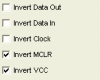
also ive tried to plug it in directly to the parallel port but that dosent help either, and i had noticed that both VCC and VPP(MCLR) led indicators go off during programming/reading
i saw some post a while ago on this forum or some other forum cant really remember, it said that RB10 pin or something like that has to be 0V in order to program a chip can some please remind me of what it was
please anyone help me got to learn PIC micro
ive decided to build this programmer a while a go and now its done and it dosent work !
, **broken link removed** a tait variant parallel port programmer, all tests specified on the website was done successfully but i cant program a F84A or the F628A it writes the code and gives me a "verify failed at address 000h !" error then when i close icprog and open it again to read the pic its blank and full of 0x3FFF
so i thought to myself that the things ive done must cause it not to work so heres what ive changed
* swapped the 7406 with a 7404 since i broke two pins from the 7406 IC trying to yank it out of the socket, assuming 7406 ~= 7404 anyone here knows whats the difference ?
* i ignored both 1nF capacitors that is just after the data line and the clock line cause i dont have any 1nF or closer value
also ive tried to plug it in directly to the parallel port but that dosent help either, and i had noticed that both VCC and VPP(MCLR) led indicators go off during programming/reading
i saw some post a while ago on this forum or some other forum cant really remember, it said that RB10 pin or something like that has to be 0V in order to program a chip can some please remind me of what it was
please anyone help me got to learn PIC micro