Continue to Site

Welcome to our site!

Electro Tech is an online community (with over 170,000 members) who enjoy talking about and building electronic circuits, projects and gadgets. To participate you need to register. Registration is free. Click here to register now.

  • Welcome to our site! Electro Tech is an online community (with over 170,000 members) who enjoy talking about and building electronic circuits, projects and gadgets. To participate you need to register. Registration is free. Click here to register now.

Need Help repairing an Electronic Composter

fieldsweeper

New Member
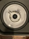
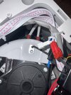
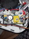
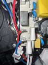
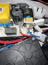
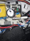
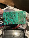
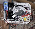
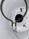
Hi all, I need some help with what is probably a simple fix. I received a composter second hand and when initiated all components work. Panel and touch screen work, motors work, fan work, the only part that does not work is the heating element. Attached are some images of the heating element and pcb connection, any help would be appreciated.
 

Attachments

  • IMG_0195.jpg
    IMG_0195.jpg
    5.2 MB · Views: 29
  • IMG_0196.jpg
    IMG_0196.jpg
    3.9 MB · Views: 28
  • IMG_0197.jpg
    IMG_0197.jpg
    4.6 MB · Views: 20
  • IMG_0198.jpg
    IMG_0198.jpg
    4.5 MB · Views: 21
  • IMG_0199.jpg
    IMG_0199.jpg
    4.7 MB · Views: 21
  • IMG_0200.jpg
    IMG_0200.jpg
    4.4 MB · Views: 20
  • IMG_0203.jpg
    IMG_0203.jpg
    5 MB · Views: 25
What is the resistance between the two heater wires, the ones with the white woven sleeving?
Here is an image attached with the multimeter reading at 0. I am a complete beginner so please help me if there is something I am doing incorrectly.
 

Attachments

  • IMG_0205.jpg
    IMG_0205.jpg
    1.3 MB · Views: 20
That is reading infinity, not zero.

If the meter is directly across the heating element and it reads the same as when not connected to anything (and the meter shows something else when it's leads are joined together) then the element has failed.
 
That is reading infinity, not zero.

If the meter is directly across the heating element and it reads the same as when not connected to anything (and the meter shows something else when it's leads are joined together) then the element has failed.
Yes, the element has definitely failed. I'm wondering (since the rest of the components are working) how I can repair the problem.
 
Ok, thanks. I just wasn't sure if I only needed to change the wires or if something was wrong with the board connection. I'll look for a new element.
Testing where you did means that the wires can't be ruled out, so it might be worth looking at where the wires join the element, but it's likely to be the element. They fail quite often.
 
Recheck Ohms or Diode test directly across circular heater terminals
Diode test will beep when voltage drop is < 2V with ~1mA . Test probes this way, then heater, if OK , trace backwards. Even a relay solder lead can be open. (black annular ring)
 
Recheck Ohms or Diode test directly across circular heater terminals
Diode test will beep when voltage drop is < 2V with ~1mA . Test probes this way, then heater, if OK , trace backwards. Even a relay solder lead can be open. (black annular ring)
Same for both tests, you can see clearly in this picture where the element failed (along with the burns on the bottom of bucket). Was hoping I could just replace the wires but I guess not. I don't have a clue where to find a replacement since it's so small only 2.5 in diameter 120v 500w.
 

Attachments

  • IMG_0206.jpg
    IMG_0206.jpg
    3.7 MB · Views: 10
Testing where you did means that the wires can't be ruled out, so it might be worth looking at where the wires join the element, but it's likely to be the element. They fail quite often.
Last question, when I go to replace the element will I also need to resolder new wires to the pcb or should the wires still be alright?
 

Latest threads

New Articles From Microcontroller Tips

Back
Top