Electro Tech is an online community (with over 170,000 members) who enjoy talking about and building electronic circuits, projects and gadgets. To participate you need to register. Registration is free. Click here to register now.
Welcome to our site! Electro Tech is an online community (with over 170,000 members) who enjoy talking about and building electronic circuits, projects and gadgets. To participate you need to register. Registration is free. Click here to register now.
please i need a detailed answer, if i add two more transistors to this circuit (as in one in the upper part and another in the lower part) what would the power or wattage be? and also are there any changes needed to be made in this circuit
It's impossible to answer because the schematic doesn't tell wich transistors you use. That is cruicial info to determine the mosfets resistance between source and drain. That's what you're asking for, right? Put in more mosfets in paralell to reduce the total resistance.
What about using bjt's instead? Probably the total efficiency will decrease (at low load), but you may be able to take out more effect. Also buying a larger transformer will help, as the iron in small transformers will saturate easier.
It's hard to answer your question without more information. But lets assume your transistors are getting real hot now or your voltage is low or both. Lets say you get 300 watts now. Add another set of transistors and you may get 400 watts. But if the transformer is only good for 300 watts you won't get any more out because it is saturated. Don't know? Give it a try you will be no worse off.
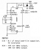
The extremely simple circuit has errors;
1) C1 is the timing capacitor in the CD4047 oscillator and is shown as a poor tolerance polarized electrolytic. But it must be non-polarized and have a value that is much less. A 0.1uF metalized plastic film 5% tolerance capacitor is good and instead of the pot a 47k resistor can be used for a 50Hz inverter or a 39k resistor can be used for a 60Hz inverter. The reason is that on Texas Instruments datasheet for the CD4047 they recommend a resistor not less than 10k ohms.
2) Spikes from the square-wave switching will occur on the 12V supply to the CD4047 which will blow it up. A resistor, capacitor and a zener diode will protect the CD4047 like in my sketch.
3) R3, R4 and R5 in your circuit and R6, R7 and R8 are also in parallel. Each group of 3 resistors can be replaced by a single resistor.
4) Each Mosfet needs a series gate resistor like R1 and R2.
5) The IRF150 is a very old Mosfet with poor spec's. Modern Mosfets have much less voltage drop and produce much less heat. If they were used then extra Mosfets are not needed for higher output power.
This site uses cookies to help personalise content, tailor your experience and to keep you logged in if you register.
By continuing to use this site, you are consenting to our use of cookies.

")