fatimauzma
New Member
hey
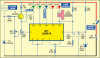
i working on a stress meter right now.i saw the circuit on electronics for you.
but my lecturer wants me to use two I.C instead of one and 10 leds instead of 5 as done in the circuit.
iam thinking of using a resistor between them.can any one pls help me redesign the given circuit
i working on a stress meter right now.i saw the circuit on electronics for you.
but my lecturer wants me to use two I.C instead of one and 10 leds instead of 5 as done in the circuit.
iam thinking of using a resistor between them.can any one pls help me redesign the given circuit