Continue to Site

Welcome to our site!

Electro Tech is an online community (with over 170,000 members) who enjoy talking about and building electronic circuits, projects and gadgets. To participate you need to register. Registration is free. Click here to register now.

  • Welcome to our site! Electro Tech is an online community (with over 170,000 members) who enjoy talking about and building electronic circuits, projects and gadgets. To participate you need to register. Registration is free. Click here to register now.

Need help with a scheme

Status
Not open for further replies.

Drogarush

New Member
Hello,

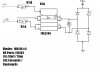
I'm a Norwegian student who currently is studying for an upcoming exam in electronics, and as a preparation, I've gotten this scheme I am having trouble with. I've figured out 2/3 of the schemes, but I just can't get this one right. Any help would be appreciated. :)
 

Attachments

  • Electronic scheme.JPG
    Electronic scheme.JPG
    42.1 KB · Views: 188
All the information you need is in the symbol. It is a buffer, the output equals the input. Check the datasheet for the drive characteristics. I think it can sink more current than it can source. The outputs are three state outputs, they can be low, or they can be high, or they can be high impedance. The enable signal goes to the box on top with small indentations. The whole idea behind the construction of those symbols was to make the function unambiguous. I guess they forgot to give the secret decoder ring.

I'm with Nigel on the potential for destruction of the part.
 
If you have an extremely weak little motor then the circuit might drive it.
The minimum source current of each buffer is 15mA and the voltage might be as low as 2V. Look in the datasheet.

So if the motor runs with 1.8V at 30mA then it is fine.
 
They use these type of circuits for B.E.A.M robots. Usually it's a 74HC240, and they stack 2 or more in parallel (yes, stack. one on top the other). The motors are tiny, often cellphone vibrator motors.
 
Status
Not open for further replies.

Latest threads

New Articles From Microcontroller Tips

Back
Top