Electro Tech is an online community (with over 170,000 members) who enjoy talking about and building electronic circuits, projects and gadgets. To participate you need to register. Registration is free. Click here to register now.
Welcome to our site! Electro Tech is an online community (with over 170,000 members) who enjoy talking about and building electronic circuits, projects and gadgets. To participate you need to register. Registration is free. Click here to register now.
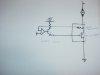
I'll ask one more time. I have a partial blower schematic and need help in identifyig the components, how they should be connected, and completing the circuit. The schematic is included as an attachment.
What are the max current and voltage rating of the blower? Do you want to control its speed? How?
What is the input voltage?
What are the opamp and transistor for? What are their part numbers?
What are the resistors for? What are their values?
Why doesn't the opamp have a power supply?
The motor is DC PM motor, 24V,17A max draw. I would like to control the speed through a digipot? to a momentary switch, on-off-onto increase/decrease blower speed. I am currently using a Critical Velocity PWM controller, to noisy, tried caps, twisted wires, etc. This is a partial schematic of a blower circuit from my Honda. I am electronically deficient, so be gentle.
My limited understanding is that through an amplifier, NPN transistor, and feedback loop, voltage can be regulated through the Power Transistor to the ground of the motor to regulate speed. The switch was not shown in the schematic(it's changed as part of an assembly) nor where/how it connects to the circuit, at least to me. I assume it must tie into the inputof the amp, but that's all I'm assuming. I have no part numbers or values, or no why these components are used. The blower in my car has worked fine for six years, so why not upgrade the components for voltage/current and use it .
The PWM controller switched fully on then switched fully off to avoid getting too hot. When it is on the voltage across the switching transistor is low so the heating of it is also low. When it is off then it isn't heating. The PWM switches very quickly so the motor doesn't vibrate but maybe not quick enough so it is heard as a whistle. Too much electrical noise? Sure, it is a switching circuit. The duty-cycle of the PWM pulses controlled the power to the motor.
Your idea to use a digi-pot to control the motor's voltage will create a lot of heat in the transistor. If the voltage to the motor is half at 12V then its current is also half at 8.5A. If a transistor is used simply as a variable resistor in series with the motor the it will also have 12V and 8.5A which is 102W of heat.
A transistor will melt if it has 102W of heat. Two transistors could share the heat but would need to have a huge heatsink.
My cars' system, which is shown in the schematic uses, I think a power transistor, some type of op amp connected to an NPN transistor. The switch in the car is an on-off-on momentary switch with a vertical chain of 7 LED's
that light up as rpm/voltage increases and extinguish as rpm/voltage decreases. This all the info I have and would like a circuit that replicates
this one. The power transistor would be in the blower airstream so thermal management isn't a problem.
I don't have accessto the IC, unless I rip the dash apart, to much work, I'm trying to buy a used AC cluster to look at. My only experience with PWM is the unit I am currently using and it is noisy. Possible to build something quieter?
This site uses cookies to help personalise content, tailor your experience and to keep you logged in if you register.
By continuing to use this site, you are consenting to our use of cookies.

")