Continue to Site

Welcome to our site!

Electro Tech is an online community (with over 170,000 members) who enjoy talking about and building electronic circuits, projects and gadgets. To participate you need to register. Registration is free. Click here to register now.

  • Welcome to our site! Electro Tech is an online community (with over 170,000 members) who enjoy talking about and building electronic circuits, projects and gadgets. To participate you need to register. Registration is free. Click here to register now.

Need help with circuit explanation (detailed)

Status
Not open for further replies.

ericson

New Member
Hello

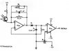
I found a schematic with a circuit with a motion sensor. Its build up by a sender and a receiver. The receiver is shown below and I need a detailed explanation of how it works. I have used a lot of time on it and studied some theory with bandpasses and peak detectors but I still have some way to go and would like a very detailed explanation but else you just tell what you know:)
 

Attachments

  • Receiver.JPG
    Receiver.JPG
    21.5 KB · Views: 165
It is an extremely simple circuit. It has a photo-transistor, a bandpass amplifier and a peak detector circuit.
How do you think it works?

1) What does the photo-transistor do when it receives light?
2) What does the first opamp do when the photo-transistor is active?
3) How does the parallel resonant LC circuit affect the gain of the first opmp?
4) What does the diode do when the first opamp is activated?
5) what does C2 do?
6) What does the second opamp do when the diode does its "thing"?
Simple stuff.
 
ok, Im looking at the circuit and i will do my best, please correct me.

As I see it, when the transistor receives light it opens up for current. There will be no voltage going into the inverting port because the non-inverting port is grounded. In the LC circuit we have a alternating current and I guess that why we have a diode.
The capacitor stores the current peak voltage. If the input voltage is larger, the op-amp output goes positive until the capacitor is charged up to the new peak value. If the input voltage is smaller, the diode keeps the capacitor from being discharged.

Thats where im at.
 
Wait a minute!
A door opens and closes. But a transistor turns on or it turns off.

When the photo-transistor turns on then the 2k resistor applies a positive current to the inverting input of the first opamp which causes its output to go negative.

The parallel LC circuit is a high impedance at its resonant frequency and the gain of an opamp depends on the ratio of its negative feedback impedance to its input impedance (2k ohms). So the gain (sensitivity) of the first opamp is high at the resonant frequency of the LC.

The output of the first opamp goes negative but it might also be modulated a little by the signal frequency. The diode charges C2 quickly to the peak voltage of the DC plus AC at the output of the first opamp. Then C2 discharges slowly by the 22k resistor.
 
Status
Not open for further replies.

Latest threads

New Articles From Microcontroller Tips

Back
Top