Continue to Site

Welcome to our site!

Electro Tech is an online community (with over 170,000 members) who enjoy talking about and building electronic circuits, projects and gadgets. To participate you need to register. Registration is free. Click here to register now.

  • Welcome to our site! Electro Tech is an online community (with over 170,000 members) who enjoy talking about and building electronic circuits, projects and gadgets. To participate you need to register. Registration is free. Click here to register now.

Need Help with latching alarm?

Status
Not open for further replies.

Nicksan

New Member
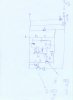
I purchased a door alarm that has one of those magnetic switches that attaches to a door and the door frame.

When I close the door, the alarm does not stay on because the magnet is activating the reed switch.

How can I modify it so the alarm stays on (for a pre-determined time or not) after the door has been shut?

I was thinking of using a 555 but not sure how to wire it up.

Thanks.
 
is it the intention that the alarm goes off when the door goes open and the activated divice stays on for a while

or is it the intention to have the alarm going off when the door gets closed and the activated device stays on for a while

what is the time lengt you looking for ??

Robert-Jan
 
Yes, I would like for the alarm to stay on for a while after the door is opened and after the door is closed, Maybe for five or ten minutes.

The problem with the design of the alarm as it is now is, When the door opens, the alarms sounds off but all you have to do is close the door to stop the alarm because the magnet opens the reed switch on the alarm.
 
if you need 5 till 10 minutes than i would use a 4060 timer ic instead of a 555
i will post you a shematic today but I am very busy at my work now so it could take a while

Robert-Jan
 
Ok quicker than i did foresee

I forgot to draw 1 diode and that's the one over the relais

i do advise you to down load also the data sheet from the 4060 as you can find out the diferent times on diferent outputs

you also can play with the capasitors conected on pin 9 and of course the resistors on pin 10

the resistor on pin 11 i would not make it smaler than 1 M:eek:hm:

sucses with building it

Robert-Jan
 

Attachments

  • TMP19.JPG
    TMP19.JPG
    187.7 KB · Views: 177
Last edited:
Thanks for the schematic. Would it be possible to downgrade the voltage required to something around 3 to 6 volts, because thats around what the alarm uses and I have no idea how to make 16 to 20 other than compiling a bulky mess of D or AA cells?
 
5 a 6 volt is fine (instead of the 7812 use the 7805) but it will effect the timing so you have to tweek a bit with the outputs or capacitors/resistors

also your relais should be a 5v one

you can make a power supply feeding from the net

transformer, bridge rectifier , capacitor feed it in the 7805 and there you go

not that complicated

Robert-Jan

i
 
Status
Not open for further replies.

Latest threads

New Articles From Microcontroller Tips

Back
Top