loup-garou
New Member
hi all,
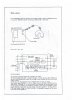
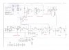
can anyone give me a liquid drop sensor schematic, I spent hours googling without finding anyone.
the kind I'm lookin for is that using photodiode pass-band, amplifier , controller and other IC (can be replaced with a PIC microcontroller)
please help me.
thanks in adavnce.
can anyone give me a liquid drop sensor schematic, I spent hours googling without finding anyone.
the kind I'm lookin for is that using photodiode pass-band, amplifier , controller and other IC (can be replaced with a PIC microcontroller
)please help me.
thanks in adavnce.