Continue to Site

Welcome to our site!

Electro Tech is an online community (with over 170,000 members) who enjoy talking about and building electronic circuits, projects and gadgets. To participate you need to register. Registration is free. Click here to register now.

  • Welcome to our site! Electro Tech is an online community (with over 170,000 members) who enjoy talking about and building electronic circuits, projects and gadgets. To participate you need to register. Registration is free. Click here to register now.

Need small rectifier design for 12v A/C Power Supply

Status
Not open for further replies.

LEDman

New Member
I have a 12v/830ma wall wart PS that produces A/C. I need to change it to D/C to power some relays and LED's (nothing too critical, although there are some audio signals going through the relay contacts). The circuit will actually draw about 300ma.

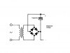
I don't know all that much about rectificaiton or electronics... but I'm thinking that one of those 4 way diode rectifers (full wave?) would do it and preserve the power level (I need to get at least 9 volts out of it to run the relays).

Questions:

1. Is this the best approach, or is there a simpler component(s) that would do the job.
2. Will I get 12volts out of this approach?
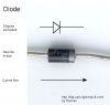
3. What diodes (specifically) would I use? I know nothing about spec'ing them... I only just understand what they do :)
 
if you can use a rectification bridge it will be good else, the following method will do the job for you.
you can use diodes(1N4001) or any 500 mA diode.
the vaule of capacitor can be 470 µf 25volt.
 

Attachments

  • untitled.JPG
    untitled.JPG
    29.8 KB · Views: 613
  • diode.jpg
    diode.jpg
    17 KB · Views: 11,198
An electrolytic is most commonly used as a filter behind a full-wave rectifier. Please note that the polarity of the posted circuit is backwards. The bottom terminal of the capacitor is positive; not the top. Electrolytic capacitors are polarized, so the + on the capacitor must be connected to the terminal of the bridge where the two cathodes come together. The negative end connects to where the two anodes come together.
 
OK... I tweaked the diagram and attached it with the tweak. Can you tell me if I have it right?

Does the +12V end up on the other leg with the capacitor reversed so I need to watch for that too?

Thanks,
 

Attachments

  • rect.gif
    rect.gif
    37 KB · Views: 368
OK... I tweaked the diagram and attached it with the tweak. Can you tell me if I have it right?

Does the +12V end up on the other leg with the capacitor reversed so I need to watch for that too?

Thanks,

Look at this image.
 

Attachments

  • rect.gif
    rect.gif
    34.6 KB · Views: 380
The output is the peak voltage (minus two diode drops) of about 15.2VDC, not 12VDC.
 
Duplicate post
 
Last edited:
OK.. now I'm a bit confused. Are you suggesting that the actual power output of the wall wart (when measured will be 15VAC giving me 15VDC? Or that something I don't understand happens when I rectify it bumping the voltage?

I have not tested this particular wall wart yet, but a couple others I checked that were marked 12v were putting out around 13v+.
 
The bridge rectifier capacitor charges to the peak AC voltage minus the diode drops of two rectifiers in series. The peak voltage of a sine wave is ≈1.4 times the RMS voltage.
 
Last edited:
OK... so if the relays that this will power are rated at a max 14.4 volts through the coil, I should be thinking about putting some resistors in there to drop the voltage back down a bit?
 
OK... so if the relays that this will power are rated at a max 14.4 volts through the coil, I should be thinking about putting some resistors in there to drop the voltage back down a bit?
Or diodes in series. Each diode will reduce the voltage by about 0.7V.
 
Status
Not open for further replies.

Latest threads

New Articles From Microcontroller Tips

Back
Top