Continue to Site

Welcome to our site!

Electro Tech is an online community (with over 170,000 members) who enjoy talking about and building electronic circuits, projects and gadgets. To participate you need to register. Registration is free. Click here to register now.

  • Welcome to our site! Electro Tech is an online community (with over 170,000 members) who enjoy talking about and building electronic circuits, projects and gadgets. To participate you need to register. Registration is free. Click here to register now.

need your asssistance on getting my ldr to light up

Status
Not open for further replies.

Dentsu

New Member
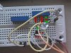
i have been trying to get my ldr to light up for some time now and i am getting frustrated. i am probably doing it wrong or maybe using a wrong component? the closes i got was when i changed the location of - from the battery to the led anode and it would light up but just for a sec then it would then die off. when i cover my ldr in this position there is a really dim glow. trying to get a dark senor working. any tips for a total newb?

50k potentiometer (15 turns)
normal white led
390 ohm resistor
bc547 transistor
unkown photoresistor
 

Attachments

  • ldr.jpg
    ldr.jpg
    20.6 KB · Views: 155
Occasionally, you will have something connected incorrectly. Occasionally, you will have a part or component that is defective.

Verify that you have the collector, base, and emitter pins of the transistor connected correctly.:

http://www.datasheetcatalog.org/datasheet/MicroElectronics/mXuwzwr.pdf

Remove the LDR from the circuit, and get the LED to work without it ... Let the transistor burn in for a while with a few milliamps of current.
Then replace the LDR ...
 
You also may want to remove the LDR from the circuit and note the Light and Dark resistances using an ohmmeter. Additionally make sure the LED is connected for correct polarity.

Ron
 
so i had time to do some testing and found out that the ldr resistance i am using is around 0.2(200M) in complete darkness and 0.92(20K) near my fluorescent bulb. i also measure the resistance at the ldr location and it was at 30k and i just lower it to better match the schematic. i need mine to go on at around 12(200K) mark. i am positive i got the anode and base, collect, etc in the right order.

i tried follow a youtube video and some guy tutorial got it working with a single 100 ohms resistor? i did the same and it burn out. i follow another video and position it the same and nothing happen until i lower the resistor and it also burn out. so i know the battery and breadboard is working.

this is my first project ever and want to get a simple one out of the way before i tackle something more advance.
 
Last edited:
If average light hitting the LDS gives you about 30 K Ohms at location they you may want to increase the pot value in the circuit to 50 or 100 K ohms. Also you can place some voltmeter leads between the LDR and Resistor (the transistor base) and ground. When the circuit is on observe the base voltage. When the base voltage to ground is about .6 to .7 volts the transistor should be turning on. When that happens the LRD should turn on.

Ron
 
some guy tutorial got it working with a single 100 ohms resistor? i did the same and it burn out
What burned out? If you have built your circuit exactly as in the top circuit of the schematic then nothing can burn out.
If you replaced the 470 ohm resistor with 100 ohm in either circuit then the LED would burn out.
 
If average light hitting the LDS gives you about 30 K Ohms at location they you may want to increase the pot value in the circuit to 50 or 100 K ohms. Also you can place some voltmeter leads between the LDR and Resistor (the transistor base) and ground. When the circuit is on observe the base voltage. When the base voltage to ground is about .6 to .7 volts the transistor should be turning on. When that happens the LRD should turn on.

Ron

hi ron, i have increase my ldr location to around 100k ohms and still nothing. my once 9v is now at 6v and the reading i get from my multimeter is 0.04(200M). i tired with a different ldr and transistor and still nothing. i didnt think a simple ldr would be this hard..
 
Something here has to be wrong. This is not a complicated circuit. Looking at the first image "LED lights when the LDR is dark". Just look at the resistors. Starting at the top we have a fixed value 10K resistor in series with a 10 K variable resistor (the one with the arrow) followed by the LDR. You are I assume wiring the variable resistor as just that correct? It should have 3 legs and the center leg is tied to one end. So the fixed resistor, the variable resistor and the LDR all form a series voltage divider.

If for example in theory all 3 resistors were 10 K and 9 volts were applied then about 3 volts would be on the base of the transistor. The numbers you posted for base voltage lead me to think maybe the pin out for the transistor is wrong? Anyway with 3 volts on the transistor base it would be full on (like a switch) and the LED would be lit. That assumes the LED polarity is correct.

When the light striking the LDR increases the LDR resistance will decrease and as that happens the current through the resistors and LDR will decrease. In turn the voltage on the base of the transistor will decrease until the transistor shuts off and the LED goes out.

Matter of fact if you simply remove the transistor from the circuit (just yank it out of the circuit) you should be able to measure the voltage at the junction of the LDR and the resistors above it and ground and watch the voltage change as the LDR goes from Light to Dark.

Ron
 
didn't know i had a reply but i think the solution is something simple like incorrectly connecting the wires so i have uploaded a picture of it current state right now. i hope this camera shot show up clearly and this is how i interpret the schematic.
 

Attachments

  • cir.jpg
    cir.jpg
    125.2 KB · Views: 125
... Suggest that you check the continuity of the 5 hole groups along the lower edge of the breadboard. If the breadboard that you are using follows standard convention, all of the wire holes along that bus are connected. Try using the lower Y bus row for ground, and the upper X bus row ... at the top of the picture ... for Vs ... or vice versa.
 
OMFG. that was the problem...it is now working perfectly. thanks a bunch!! i knew it must have been something stupid like this. :)
 
Status
Not open for further replies.

Latest threads

New Articles From Microcontroller Tips

Back
Top