Continue to Site

Welcome to our site!

Electro Tech is an online community (with over 170,000 members) who enjoy talking about and building electronic circuits, projects and gadgets. To participate you need to register. Registration is free. Click here to register now.

  • Welcome to our site! Electro Tech is an online community (with over 170,000 members) who enjoy talking about and building electronic circuits, projects and gadgets. To participate you need to register. Registration is free. Click here to register now.

Needing help with delay times on a 12f509

Status
Not open for further replies.

Darkstar64

New Member
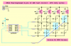
Hey well im code is almost complete but I am missing one more thing and thats the delay times im a little confused on them so here is what im trying to achieve I multiplexed 12 leds with 4 outputs and 2 inputs to control what operation is exec anyways since only one LED can be on at a time I need them to cycle fast so that it looks like there all on at the same time but really there not they need to be cycling for 3-4 seconds so lets use a letter as a example say J the letter J needs to be on for 3-4 seconds but as stated before only one LED can be on at one time so im unsure how to do this. This is what I have so far I also included the Delay subroutine of 10ms and one of the LED subroutines as well and last but not least the code I have so far this only loops 13 times im not sure how long that is but it needs to loop for 3-4 seconds so the J stays on for 3-4 seconds I also want to add in curcuit programming what do I need electronic wise to seperate the pins from the main electronics so that the PIC can be programmed I was told you couldn't just add the wires you had too seperate the PIC from the main electonics first before you did any programming otherwise it would fry the PIC

Code:
;****************** Delay Subroutine ( 10 ms )

delay10					; Delay W x 10ms 
		movwf	dc3		; Delay = 1 + W x (3 + 10009 + 3) - 1 + 4 -> W x 10.015ms
dly2	movlw	.13		; Repeat inner loop 13 times
		movwf	dc2		; -> 13 x (767 + 3) - 1 = 10009 cycles
		clrf	dc1		; Inner loop = 256 x 3 - 1 = 767 cycles
dly1		decfsz	dc1,f
		goto	dly1
		decfsz	dc2,f		; End middle loop
		goto	dly1
		decfsz	dc3,f		; End outer loop
		goto	dly2
		retlw	0

Code:
;****************** LED Subroutine

lightledA
		movlw	b'111010'	; Configure GP4 and GP1 as input
		tris	GPIO
		movlw	b'000001'	; Change corresponding bit of GP0 to 1
		movwf	GPIO		; Writes 1 to GP0
		movlw	delaytime		; Get from dealytime variable
		call	delay10		; Delay of 50 x 10ms = 500ms or .5s
		movlw	shadow	; Change corresponding bit of GP0 to 0
		movwf	GPIO
		movlw	b'101000'	; Configure GP0,GP1,GP2,GP4 to outputs
		tris	GPIO			; Write 0 to GP0
		retlw	0

Code:
                movlw	.13		; Loops 13 times
		movwf	cv1		; Writes 13 to cv1
cv5	        call    lightledC	  ; Letter J
		call	lightledB
		call	lightledA
		call	lightledD
		call	lightledG
		call	lightledG
		call	lightledH
		call	lightledI
		call	lightledJ
		call	lightledK
		call	lightledL
		decfsz	cv1,f	; Decrement counter is set to 13
		goto	cv5	    ; If Decrement counter is not 0 then repeats loop
 
Last edited:
If you can post a circuit it would help.

As you can only light one LED at a time, if you need say 10 LEDs for a letter, you need to light each LED more often than 100 times a second. I suggest 1000 times a second, so your 10 ms delay is far too long, and if you use 0.5 s it won't even look like a letter, it will just look like a load of lights turning on in sequence. You should light each LED for about 100 µs.

For each letter you need to flash each LED about 3000 - 4000 times. With an 8 bit PIC you need to have two nested counters.

In your code you wrote:-

Code:
		movlw	delaytime		; Get from dealytime variable
		call	delay10		; Delay of 50 x 10ms = 500ms or .5s

I think that there may be some confusion about variables and constants. In this code, delaytime is a constant, so the w is made equal to whatever you defined delaytime as.

If you want delaytime to be a variable, you have to define what register is used for delaytime, delaytime should be set by the code before you execute that part of the code, and then the code should be:-

Code:
		movf	delaytime, w		; Get from dealytime variable
		call	delay10		; Delay of 50 x 10ms = 500ms or .5s
 
srry I can't get you the circuit as I don't have a scanner and its just on paper sketched up. Here is the whole code I understand what you mean by each LED being on for 100 µs. But I also need the delay for the rain to be 250ms per LED being lit up as I want 4 leds to turn on in 1 second so im thinking what can I do about that? Since everthing is being called on the 12 lightled Subroutines im kinda stuck because I need the 100 µs delay for the Letters but a 250ms delay for the Rain is there any way this can be done or do I just have to forget about one of them ? or is there a way to skip some of the 10ms delay if a certain action was taken say the press of GP5 makes the delay .25 x 10ms delay and the press of GP3 makes the delay 100 µs ? or is there maby a way to add 2 delays together for a 250ms delay so add the 100 µs delay to the 10ms delay for just the rain subroutine? Or maby even change the delay10 name so at the start of rain maby define delay10 as something different instead of the 100 µs delay ? im not clear on this if theres even a way to do it. Also with the delaytime Variable I used it so that I can change the delay of the lightled Subroutines without having to go to each one and changing them I can just change one variable and everything goes off that did I do it correctly ? ok now to loop for the letters I would need to do something like this to get it to loop if im correct at the math say 11 LED's and the delay before one LED turns off is 100 µs to light them all it would take 1870 µs or 1.87ms so it would need to loop about 535 times for 1 second so for 2 seconds it would need to loop 1070 times per letter ahah any help on this guys im kinda stuck on the assembly on this one it took me a hour just to sort out the loop of 13 times haha


Also if you undersand what im trying to do if theres a better way please tell me haha it would make things alot easyer to work with thanks :)

Code:
    	list	p=12F509	; list directive to define processor
#include	<p12F509.inc> 		; processor specific variable definitions

		__config _MCLRE_ON & _CP_OFF & _WDT_OFF & _IntRC_OSC

; '__CONFIG' directive is used to embed configuration word within .asm file.  
; The lables following the directive are located in the respective .inc file.   
; See respective data sheet for additional information on configuration word.  


		cblock	0x07
;***** VARIABLE DEFINITIONS  
dc1		; Delay Loop Counters
dc2		
dc3
cv1		; Loop Counter Variables
cv2
cv3
shadow	; Shadow variable used in rain to keep all top leds on or for cycle to resest all bits to 0
delaytime	; Adjustable delay variable		
		endc


;************************************************* *********************  
; Internal RC calibration value is placed at location 0x3FF by Microchip  
; as a movlw k, where the k is a literal value.  

		org	0
MAIN		
		movwf	OSCCAL		; update register with factory cal value 


;******** Main Code

start
        movlw   b'101000'       ; Configure only GP3 and GP5 as a input
        tris    GPIO

        goto    testbut

loop
waitup  movlw   .2
        call    delay10         ; Delay of 20ms to debounce EITHER switch
        btfsc   GPIO,3          ; Is switch 3 pressed?
        goto    waitup          ;       Yes, wait 20ms and test again
        btfsc   GPIO,5          ; Is switch 5 pressed?
        goto    waitup          ;       Yes, wait 20ms and test again
                                 ; At this point both switches are up

testbut btfss   GPIO,3          ; skip if button NOT pressed on GP3 ( GP3 low )
        goto    got3
        btfsc   GPIO,5          ; skip if button IS pressed on GP5 ( GP5 low )
        goto    testbut         ;       Otherwise wait for either button


got5    call    counter            ; Calls counter Subroutine that loops the subroutine X number of times
        goto    waitup          ;       ensure button up on return from counter

got3    call    counter2           ; Calls counter2 Subroutine that loops the subroutine X number of times

        goto    waitup          ;       ensure button up on return from counter2


        goto    loop

;******************* Loops the code X # of times to change the loop amout change .13 or # to amount of times you want looped

counter
		movlw	.13		; Loops 13 times
		movwf	cv1		; Writes 13 to cv1
cv5		call	Rain	; Calls the Rain Subroutine
		decfsz	cv1,f	; Decrement counter is set to 13
		goto	cv5	    ; If Decrement counter is not 0 then repeats loop

counter2
		movlw	.13		; Loops 13 times
		movwf	cv3		; Writes 13 to cv1
cv4		call	Sam	    ; Calls the Sam Subroutine
		decfsz	cv3,f	; Decrement counter is set to 13
		goto	cv4	    ; If Decrement counter is not 0 then repeats loop


;******** Main Subroutine's / Effects

Rain

		movlw	b'000000'
		movwf	shadow
		movlw	.2
		movwf	delaytime
		call	lightledA
		call	lightledD
		call	lightledG
		call	lightledJ
		movlw	.9
		call	delay10
		movlw	.3
		movwf	delaytime
		call	lightledC
		call	lightledF
		call	lightledI
		call	lightledL
		movlw	.9
		call	delay10
		movlw	.9
		call	delay10
		movlw	.9
		movwf	delaytime
		call	lightledA
		call	lightledD
		call	lightledG
		call	lightledJ
		movlw	.9
		call	delay10
		movlw	.9
		call	delay10
		movlw	.9
		call	delay10
		movlw	.4
		movlw	delaytime
		call	lightledB
		call	lightledE
		call	lightledH
		call	lightledK
		goto	Rain

Sam

		movlw	b'000000'
		movwf	shadow
		movlw	.01
		movwf	delaytime
		call	lightledC	; Letter S
		call	lightledB
		call	lightledA
		call	lightledD
		call	lightledG
		call	lightledG
		call	lightledH
		call	lightledI
		call	lightledJ
		call	lightledK
		call	lightledL
		movlw	.9
		call	delay10
		call	lightledB	; Letter A
		call	lightledD
		call	lightledF
		call	lightledG
		call	lightledI
		call	lightledH
		call	lightledJ
		call	lightledL
		movlw	.9
		call	delay10
		call	lightledJ	; Letter M
		call	lightledG
		call	lightledD
		call	lightledA
		call	lightledE
		call	lightledC
		call	lightledF
		call	lightledI
		call	lightledL
		goto	Sam


;************* Subroutines

;****************** Delay Subroutine ( 10 ms )

delay10					; Delay W x 10ms 
		movwf	dc3		; Delay = 1 + W x (3 + 10009 + 3) - 1 + 4 -> W x 10.015ms
dly2	movlw	.13		; Repeat inner loop 13 times
		movwf	dc2		; -> 13 x (767 + 3) - 1 = 10009 cycles
		clrf	dc1		; Inner loop = 256 x 3 - 1 = 767 cycles
dly1		decfsz	dc1,f
		goto	dly1
		decfsz	dc2,f		; End middle loop
		goto	dly1
		decfsz	dc3,f		; End outer loop
		goto	dly2
		retlw	0

;****************** LED Subroutines 

lightledA
		movlw	b'111010'	; Configure GP4 and GP1 as input
		tris	GPIO
		movlw	b'000001'	; Change corresponding bit of GP0 to 1
		movwf	GPIO		; Writes 1 to GP0
		movlw	delaytime		; Get from dealytime variable
		call	delay10		; Delay of 50 x 10ms = 500ms or .5s
		movlw	shadow	; Change corresponding bit of GP0 to 0
		movwf	GPIO
		movlw	b'101000'	; Configure GP0,GP1,GP2,GP4 to outputs
		tris	GPIO			; Write 0 to GP0
		retlw	0

lightledB
		movlw	b'001110'	; Configure GP1 and GP2 as inputs
		tris	GPIO
		movlw	b'000001'	; Change corresponding bit of GP0 to 1
		movwf	GPIO		; Writes 1 to GP0
		movlw	delaytime		; Get from dealytime variable
		call	delay10		; Delay of 50 x 10ms = 500ms or .5s
		movlw	shadow	; Change correspoding bit of GP1 to 0
		movwf	GPIO
		movlw	b'101000'	; Configure GP0,GP1,GP2,GP4 to outputs
		tris	GPIO
		retlw	0

lightledC
		movlw	b'001110'	; Configure pins GP1 and GP2 to inputs
		tris	GPIO
		movlw	b'010000'	; Change corresponding bit of GP4 to 1
		movwf	GPIO		; Writes 1 to GP4
		movlw	delaytime		; Get from dealytime variable
		call	delay10		; Delay of 50 x 10ms = 500ms or .5s
		movlw	shadow	; Change correspoding bit of GP4 to 0
		movwf	GPIO
		movlw	b'101000'	; Configure GP0,GP1,GP2,GP4 to outputs
		tris	GPIO
		retlw	0

lightledD
		movlw	b'011001'	; Configure pins GP1 and GP4 to inputs
		tris	GPIO
		movlw	b'000100'	; Change corresponding bit of GP2 to 1
		movwf	GPIO		; Writes 1 to GP2
		movlw	delaytime		; Get from dealytime variable
		call	delay10		; Delay of 50 x 10ms = 500ms or .5s
		movlw	shadow	; Change correspoding bit of GP2 to 0
		movwf	GPIO
		movlw	b'101000'	; Configure GP0,GP1,GP2,GP4 to outputs
		tris	GPIO
		retlw	0

lightledE
		movlw	b'011001'	; Configure pins GP0 and GP4 to inputs
		tris	GPIO
		movlw	b'000010'	; Change corresponding bit of GP1 to 1
		movwf	GPIO		; Writes 1 to GP1
		movlw	delaytime		; Get from dealytime variable
		call	delay10		; Delay of 50 x 10ms = 500ms or .5s
		movlw	shadow	; Change correspoding bit of GP2 to 0
		movwf	GPIO
		movlw	b'101000'	; Configure GP0,GP1,GP2,GP4 to outputs
		tris	GPIO
		retlw	0

lightledF
		movlw	b'001101'	; Configure pins GP0 and GP2 to inputs
		tris	GPIO
		movlw	b'010000'	; Change corresponding bit of GP4 to 1
		movwf	GPIO		; Writes 1 to GP4
		movlw	delaytime		; Get from dealytime variable
		call	delay10		; Delay of 50 x 10ms = 500ms or .5s
		movlw	shadow	; Change correspoding bit of GP4 to 0
		movwf	GPIO
		movlw	b'101000'	; Configure GP0,GP1,GP2,GP4 to outputs
		tris	GPIO
		retlw	0

lightledG
		movlw	b'011100'	; Configure pins GP2 and GP4 to inputs
		tris	GPIO
		movlw	b'000010'	; Change corresponding bit of GP1 to 1
		movwf	GPIO		; Writes 1 to GP1
		movlw	delaytime		; Get from dealytime variable
		call	delay10		; Delay of 50 x 10ms = 500ms or .5s
		movlw	shadow	; Change correspoding bit of GP0 to 0
		movwf	GPIO
		movlw	b'101000'	; Configure GP0,GP1,GP2,GP4 to outputs
		tris	GPIO
		retlw	0

lightledH
		movlw	b'011001'	; Configure pins GP0 and GP4 to inputs
		tris	GPIO
		movlw	b'000100'	; Change corresponding bit of GP2 to 1
		movwf	GPIO		; Writes 1 to GP2
		movlw	delaytime		; Get from dealytime variable
		call	delay10		; Delay of 50 x 10ms = 500ms or .5s
		movlw	shadow	; Change correspoding bit of GP2 to 0
		movwf	GPIO
		movlw	b'101000'	; Configure GP0,GP1,GP2,GP4 to outputs
		tris	GPIO
		retlw	0

lightledI
		movlw	b'001011'	; Configure pins GP0 and GP1 to inputs
		tris	GPIO
		movlw	b'000110'	; Change corresponding bit of GP1 to 1
		movwf	GPIO		; Writes 1 to GP1
		movlw	delaytime		; Get from dealytime variable
		call	delay10		; Delay of 50 x 10ms = 500ms or .5s
		movlw	shadow	; Change correspoding bit of GP1 to 0
		movwf	GPIO
		movlw	b'101000'	; Configure GP0,GP1,GP2,GP4 to outputs
		tris	GPIO
		retlw	0

lightledJ
		movlw	b'011100'	; Configure pins GP2 and GP4 to inputs
		tris	GPIO
		movlw	b'001001'	; Change corresponding bit of GP0 to 1
		movwf	GPIO		; Writes 1 to GP0
		movlw	delaytime		; Get from dealytime variable
		call	delay10		; Delay of 50 x 10ms = 500ms or .5s
		movlw	shadow	; Change correspoding bit of GP1 to 0
		movwf	GPIO
		movlw	b'101000'	; Configure GP0,GP1,GP2,GP4 to outputs
		tris	GPIO
		retlw	0

lightledK
		movlw	b'011001'	; Configure pins GP0 and GP4 to inputs
		tris	GPIO
		movlw	b'000010'	; Change corresponding bit of GP1 to 1
		movwf	GPIO		; Writes 1 to GP1
		movlw	delaytime		; Get from dealytime variable
		call	delay10		; Delay of 50 x 10ms = 500ms or .5s
		movlw	shadow	; Change correspoding bit of GP0 to 0
		movwf	GPIO
		movlw	b'101000'	; Configure GP0,GP1,GP2,GP4 to outputs
		tris	GPIO
		retlw	0

lightledL
		movlw	b'001110'	; Configure pins GP0 and GP1 to inputs
		tris	GPIO
		movlw	b'010000'	; Change corresponding bit of GP4 to 1
		movwf	GPIO		; Writes 1 to GP4
		movlw	delaytime		; Get from dealytime variable
		call	delay10		; Delay of 50 x 10ms = 500ms or .5s
		movlw	shadow	; Change correspoding bit of GP0 to 0
		movwf	GPIO
		movlw	b'101000'	; Configure GP0,GP1,GP2,GP4 to outputs
		tris	GPIO
		retlw	0
					
		end
 
Last edited:
Ok well since im only needing 12 LED's I changed the Diagram please tell me if this is correct

Now Im thinking of making it so that there is a subroutine to turn on the LED's and then a seperate one to turn them off so all have 24 small subroutines then I can make the delay loops seperate and I could have as many as I needed.

But for the loops im not sure how to do them I can make the bigger loops just not the small ones I need one that is 100 µs and then the 10ms one that I already have can someone help me out with the 100 µs one in assembler. Thanks alot guys for all the help its coming together nicely.

Also how would I go about looping the code a number of times lets say for Rain I need to to loop lets say for 10-20 seconds it needs to keep repeating the same code I really don't want to have to copy and past the whole thing I would rather just make a loop and call the Rain subroutine so it is more understandable also the code/help for this must be in assembler as well thanks

Also one more thing what would I put between the main curcuit (LED's transistors is the main curcuit etc ) so that I can use in cuircuit programming

The Curcuit Diagram please tell me if this is correct or if some trace is missing or not looking right

Thanks alot of all the help guys its really making me understand it alot more then I use to and I mean alot ahaha


**broken link removed**
 
Last edited:
Srry for the double post but I can't seem to find any way to get 12 LED's with 4 pins chalieplexed in a good square patter even with a common it has been bugging me all night ive tried almost 10 times already haha any help from the experts at this Im useing the PWM demo Circuit as a quick look over to see what needs to be done but for some reason I always end up having 1 led turning on another LED when its on and I can't seem to get past this and its doing it for 2 LED's
 
If you look at the post by Mike K8LH (link), he uses charlieplexed displays and has a nice way of representing them. Actually, I can post his diagram here,
charlie-detail-png.21530


If you look at the 4 by 4 region in the top corner and remove the diagonal LEDs (and the transistors), you have the 12 LED display you are trying to produce. The diagram also makes clear that more than one LED can be lit at one time.

Mike.
 
I suspect one way to drive a multiplexed display on a 12-bit core device (no interrupt capability) might be to build the program around an isochronous display loop;

Code:
;
;  GPR registers -> 07..1F (bank 0) and 30..3F (bank 1)
;
column0 equ     0x07            ; display column 0 data ---D-DD-
column1 equ     0x08            ; display column 1 data ---D-D-D
column2 equ     0x09            ; display column 2 data ---D--DD
column3 equ     0x0A            ; display column 3 data -----DDD

#define led01   column0,4       ;
#define led02   column0,1       ;
#define led03   column0,2       ;
#define led04   column1,0       ;
#define led05   column1,4       ;
#define led06   column1,2       ;
#define led07   column2,0       ;
#define led08   column2,1       ;
#define led09   column2,4       ;
#define led10   column3,0       ;
#define led11   column3,1       ;
#define led12   column3,2       ;
Code:
;******************************************************************
;  refresh display at 125 Hz (8 msecs)                            *
;                                                                 *
Display
        movlw   0x3F            ;                                 |B0
        tris    GPIO            ; blank the display               |B0
        movlw   b'00000001'     ; column 0                        |B0
        movwf   GPIO            ; set output pattern              |B0
        iorwf   column0,W       ; get column data bits            |B0
        xorlw   0xFF            ; invert all                      |B0
        tris    GPIO            ; display column 0                |B0
        DelayCy(2*msecs-7)      ; delay 2 msecs minus 7 cycles    |B0
        movlw   0x3F            ;                                 |B0
        tris    GPIO            ; blank the display               |B0
        movlw   b'00000010'     ; column 1                        |B0
        movwf   GPIO            ; set output pattern              |B0
        iorwf   column1,W       ; get column data bits            |B0
        xorlw   0xFF            ; invert all                      |B0
        tris    GPIO            ; display column 1                |B0
        DelayCy(2*msecs-7)      ; delay 2 msecs minus 7 cycles    |B0
        movlw   0x3F            ;                                 |B0
        tris    GPIO            ; blank the display               |B0
        movlw   b'00000100'     ; column 2                        |B0
        movwf   GPIO            ; set output pattern              |B0
        iorwf   column2,W       ; get column data bits            |B0
        xorlw   0xFF            ; invert all                      |B0
        tris    GPIO            ; display column 2                |B0
        DelayCy(2*msecs-7)      ; delay 2 msecs minus 7 cycles    |B0
        movlw   0x3F            ;                                 |B0
        tris    GPIO            ; blank the display               |B0
        movlw   b'00010000'     ; column 3                        |B0
        movwf   GPIO            ; set output pattern              |B0
        iorwf   column3,W       ; get column data bits            |B0
        xorlw   0xFF            ; invert all                      |B0
        tris    GPIO            ; display column 3                |B0
        DelayCy(2*msecs-9)      ; delay 2 msecs minus 9 cycles    |B0
        goto    Display         ;                                 |B0
In practice you would probably make the Display code a subroutine by replacing the last two lines with a retlw 0 instruction. Your main program would be responsible for testing and debouncing switches, setting up LED patterns, and counting display cycles. And, it would need to do all this within exactly 2 msecs from the last (call Display) column 3 TRIS operation and the next (call Display) column 0 TRIS operation.

Writing isochronous code is not an easy task even for veteran programmers (grin).

Good luck. Mike
 

Attachments

  • Charlie 12.PNG
    Charlie 12.PNG
    38.8 KB · Views: 2,772
Last edited:
By the way, here is the code I used for a delay subsystem for 12-bit core. It requires that you initialize the tmrl variable to a value of -1 in the initialization section of the program before using the function.

Mike

Code:
;
;  variables
;
tmrh    equ     0x0B            ; DelayCy()
tmrl    equ     0x0C            ; DelayCy()
;
;  constants
;
clock   equ     4               ; clock frequency in MHz
usecs   equ     clock/4         ; cycles/usec multiplier
msecs   equ     usecs*1000      ; cycles/msec multiplier
;
;  macro
;
DelayCy macro   cycles          ; cycles (Tcy), minimum 16
        movlw   high((cycles-16)/4)+1
        movwf   tmrh
        movlw   low ((cycles-16)/4)+1
        call    DelayLo-(cycles%4)
        endm
Code:
;
;  Delay(16..262159 Tcy) subroutine   Mike McLaren, K8LH, Aug'08  *
;                                                                 *
Delay.16
        nop                     ; entry point for delay%4 == 3    |B0
        nop                     ; entry point for delay%4 == 2    |B0
        nop                     ; entry point for delay%4 == 1    |B0
DelayLo addwf   tmrl,W          ; subtract 4 cycle loop time      |B0
        skpz                    ; borrow?  yes, skip, else        |B0
        goto    DelayLo         ; do another loop                 |B0
        nop                     ;                                 |B0
DelayHi addwf   tmrl,W          ; subtract 4 cycle loop time      |B0
        decfsz  tmrh,F          ; done?  yes, skip, else          |B0
        goto    DelayLo         ; do another loop                 |B0
        goto    $+1             ; burn off 2 cycles               |B0
        retlw   0               ;                                 |B0
 
Last edited:
Ok ya srry forgot to post that I have the way im going to do it I just have to adjust some code and I don't mind looping it like 1000 times ahaha to get the letters to show I just need help with the 100 µs delay loop and thats pretty much it after that I already have the 1000 time loop im going to be using a few loops inside each other for that one and thanks for the diagram I might take a few things off that and add it to mine might make things alot easyer and I don't have a 12-bit PIC at the moment just a 8-bit so some of the code is new and I haven't seen it before so ya all look into it more and all post again when I have my finished Code, Diagram thanks alot guys
 
Ok everything seems to be done I made the 100 µs delay here is the code for it if there is something wrong with it let me know please

Code:
;******************	Delay Subroutine ( 100 µs )

delay100				; Delay W x 100 µs
		movlw	.25		; Delay = ( N x 4 - 1 + 2 cycles = N x 4 + 1 )
		movwf	dc4		; Writes 25 or N to register
dc5		nop				; No Operation
		decfsz	dc4,f	; Decrement Counter
		goto	dc5	    ; If Decrement Counter is 0 then skips this if its not 0 then it loops untill 0
		retlw	0

Now you where saying that for 1 second of a letter being on I would have to loop each LED 1000 times now is that each LED or can I loop the Who Letter subroutine so it would look something like this. ( Im just useing the delay loop as the example but taking out the nop and putting in a call instead ) .

Now am I correct to say that I can only ever loop 255 times with a 8-bit PIC so I would then need to put a loop inside a loop to get the 1000 times needed ? Also how would I go about doing this then I confused myself last night thinking of the time it takes to light the LED then the delay then Turning it off so im unsure if I add that into the equation to figure out how many times it needs to be looped do you understand what I mean ? Anyways here is the new LED Code well at least some of it this is for the letter S and at the end is a .5s delay for between letters im still quite confused as to what I need to loop do I loop the Subroutine 1000 times ? because I can't loop the LED 1000 times because only one LED can be on at a time and if I loop one LED then it would just cycle though and not look like a letter ?

Code:
Sam

		call	LED_ON_C	; Letter S
		call	delay100
		call	LED_OFF		
		call	LED_ON_B
		call	delay100
		call	LED_OFF
		call	LED_ON_A
		call	delay100
		call	LED_OFF
		call	LED_ON_D
		call	delay100
		call	LED_OFF
		call	LED_ON_G
		call	delay100
		call	LED_OFF
		call	LED_ON_G
		call	delay100
		call	LED_OFF
		call	LED_ON_H
		call	delay100
		call	LED_OFF
		call	LED_ON_I
		call	delay100
		call	LED_OFF
		call	LED_ON_J
		call	delay100
		call	LED_OFF
		call	LED_ON_K
		call	delay100
		call	LED_OFF
		call	LED_ON_L
		call	delay100
		call	LED_OFF
		movlw	.244
		call	delay10		; Delay of .5s
 
Not sure what method you're using and what you're trying to do but it seems whatever you're trying to do you may be doing it "the hard way".

Can you explain what you're trying to do? Are you trying to display a letter using a group of 12 LEDs? If so, can you show us how you have the LEDs laid out to form letters?

Do you have 12 LEDs formed in a straight line for a moving POV (persistence of vision) device?

Mike
 
Last edited:
You seem to be ignoring the recommendation that you can light up to three LEDs in a single column (see previous drawing with column drivers) at one time and sequence through all four columns to easily refresh the entire display.

You should be able to set all 12 LED bits the way you want, hi or lo, and then call a subroutine to multiplex and display the data on the LEDs for some period of time.

Show us how you have the LEDs laid out to form letters and we'll provide an example and try to help you understand the concept as best we can.

Mike
 
Last edited:
Sure all draw it up in Auto Cad since its the only thing I have at the moment that will do a good job at this and the only problem with the idea your suggesting with the colum is I have no idea how to write the code for something like that and also with the schymatics I drew up for the idea your suggesting I always end up with about 4 LED's that that would turn on other LED's if they were turned on so here is the schymatic of what im trying to do as well as a chart to show what each pins state has to be for each LED

Also if you explain how its done a little more with your idea I might be able to pick it up and use it but I just don't understand how you could light the LED's in a colum when if you were to enable the same pins it doesn't turn on 2 LED's and even then I need 5 pins and I have 4 to work, the 5th pin is the common on your diagram that's why it works so ya here is everything maby this might help you be able to help me haha:)

The Layout

**broken link removed**
 
Last edited:
There is no 5th pin on my diagram. Please pay closer attention. My 4 pin 12 LED matrix is using the same pins you're using.

charlie-12-png.21589


I'm trying to get you to show us how your LEDs are physically laid out. Please show us how they're physically laid out so that we can see how you represent a letter with the LEDs.

Mike
 
Last edited:
This circuit of yours will not work and your logic truth tables says GP3 instead of GP4.

**broken link removed**
 
Last edited:
O haha I see now wow can't belive I didn't get it untill now basically instead of all the LED subroutines why not just change the bits so that I can light up 3 LED's in one colum with 2 lines of code instead of like 10-15 makes much more sense now and too loop the whole display I would only need to loop 8 lines of code 2 for each colum 1000 times a second makes complete sense now here is what I have so far is this right or am I still doing something wrong hahaha this is the code I have so far for the Name Sam I only have S and A done but im seeing some problems as I will try to tell you don't know how to get around them yet like this for instance lighting up Q4 fully will cause Q3 to light up as well am I correct on this using the following code and you did say you could light up too 3 LED's in each row so here it goes now I only want 10 and 12 lit in Q4 under this is the Code I have so far for Sam once again S and A are done still working on M I also tried to loop it 1000 times don't know if this is the correct way to do so each loop, loops 256 times so I needed 4 loops to get 1000 so its after this little bit of code also when I clarify the Variables at the start of the code for the sc variables can I just put comas between them like so sc,sc1,sc2,sc3 so that I don't have to waste like 10-15 lines just to clarify them

Code:
                movlw	b'010111'	; Letter A Q3 Completly lit
		movwf	GPIO
		call	delay100
		movlw	b'010101'	; Letter A Q4 LED #'s 10,12 lit
		movwf	GPIO
		call	delay100


Code:
Sam
		
		
		clrf	sc			; Sets Counter's loop amount to 256
		clrf	sc1
		clrf	sc2
		clrf	sc3
letS	        movlw	b'000000'	; Clears all LED's to low
		movwf	GPIO
		call	delay100
		movlw	b'010111'	; Letter S Q1 Completly lit
		movwf	GPIO
		call	delay100
		movlw	b'000011'	; Letter S Q2 LED #4 lit
		movwf	GPIO
		call	delay100
		movlw	b'010111'	; Letter S Q3 Completly lit
		movlw	GPIO
		call	delay100
		movlw	b'010111'	; Letter S Q4 Completly lit
		movwf	GPIO
		call	delay100
		decfsz	sc,f		; Inner Loop Counter
		goto	letS
		decfsz	sc1,f		; 1st Middle Loop Counter
		goto	letS
		decfsz	sc2,f
		goto	letS
		decfsz	sc3,f
		goto	letS
 
Last edited:
Srry for the double post but does this look correct? it loops 1000 times in 1 second using the setup you have also with the same numbers
 
Last edited:
Status
Not open for further replies.

New Articles From Microcontroller Tips

Back
Top