ghostman11
Well-Known Member
i tried to pos this is projects but got told i dont have the right privillages to post there!!!! so its here insted.
ok so i had enough LED flashing and wanted to do something that would actualy be useful to me so here it is.................
one of the projects i am working on in conjuction with someone else invilves the use of a test incubator i have set up, its somewhat smaller the normal ones i use on the farm and only holds about 250 - 300 eggs tops,
we have however a problem with line voltage and spikes here and as the test incubator is pc controlled with a fair bit of sophisticated control units on it, it is prone to crashing, another problem we have is because this unit is smaller than what we normaly use the heating elements we use on the other incubators wont fit!! see we have had to resort to light bulbs, wich tend to blow very quickly with the constantly being switched on and off every 1-2 mins, also we get very short power outs of normally no more than 3-4 mins but the controll pc's dont always restart when the power returns.
so my solution...................
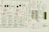
i am designing and building a monitoring system.. basicaly what it does is check that both light bulbs are working when they are ment to and if it finds 1 or both blown it switches in a back up bulb (a spare for each bulb), it also checks to make sure the PSU that runs the K190 PC temp control units is working again if it finds a fault it switches in a spare PSU, it also monitors the pc to make sure it has power and is working if its not then it reboots the pc, should the monitor unit loes its own seperate power supply then it auto switches onto the main power net, the whole thing has a LCD readout to let you know whats going on and warn of any faults and what actions its taking, there are also warning and indication LEDS and an a audible warning system (ok a speaker") ) i have included a diagram and before too many get pointed out i know there are a few mistakes on it wich i will correct.
) i have included a diagram and before too many get pointed out i know there are a few mistakes on it wich i will correct.
so far i have tested most of the main systems on the BB and they work at present i am codeing in C wich i have only just begun, although i have been getting help from another member on here. but mostly its my own work except for the LCD driver wich was origanaly from pommie for the june bug and has been somewhat modified by 3v0 for me, he also showed me how to add the sound routine.
i wont add the code on here for a couple of days as it still needs alot of work and i would rather wait before you all laugh at it lol, i should be ready to actualy put it all on strip board by tuesday (work permitting), and i will post updates. the disgram is a bit crap as i dont really know how to use proteus yet so its my first serious attemp at a diagram... anyway comments good or bad always welcome
**broken link removed**
i forgot to mention i am using the pic 18f4685 for this project and not the pic in the diagram, i used the one in the diagram to draw it as proteus didnt have the 4685 in its libray but the one i used has the same pin ports
ok so i had enough LED flashing and wanted to do something that would actualy be useful to me so here it is.................
one of the projects i am working on in conjuction with someone else invilves the use of a test incubator i have set up, its somewhat smaller the normal ones i use on the farm and only holds about 250 - 300 eggs tops,
we have however a problem with line voltage and spikes here and as the test incubator is pc controlled with a fair bit of sophisticated control units on it, it is prone to crashing, another problem we have is because this unit is smaller than what we normaly use the heating elements we use on the other incubators wont fit!! see we have had to resort to light bulbs, wich tend to blow very quickly with the constantly being switched on and off every 1-2 mins, also we get very short power outs of normally no more than 3-4 mins but the controll pc's dont always restart when the power returns.
so my solution...................
i am designing and building a monitoring system.. basicaly what it does is check that both light bulbs are working when they are ment to and if it finds 1 or both blown it switches in a back up bulb (a spare for each bulb), it also checks to make sure the PSU that runs the K190 PC temp control units is working again if it finds a fault it switches in a spare PSU, it also monitors the pc to make sure it has power and is working if its not then it reboots the pc, should the monitor unit loes its own seperate power supply then it auto switches onto the main power net, the whole thing has a LCD readout to let you know whats going on and warn of any faults and what actions its taking, there are also warning and indication LEDS and an a audible warning system (ok a speaker
) i have included a diagram and before too many get pointed out i know there are a few mistakes on it wich i will correct.so far i have tested most of the main systems on the BB and they work at present i am codeing in C wich i have only just begun, although i have been getting help from another member on here. but mostly its my own work except for the LCD driver wich was origanaly from pommie for the june bug and has been somewhat modified by 3v0 for me, he also showed me how to add the sound routine.
i wont add the code on here for a couple of days as it still needs alot of work and i would rather wait before you all laugh at it lol, i should be ready to actualy put it all on strip board by tuesday (work permitting), and i will post updates. the disgram is a bit crap as i dont really know how to use proteus yet so its my first serious attemp at a diagram... anyway comments good or bad always welcome
**broken link removed**
i forgot to mention i am using the pic 18f4685 for this project and not the pic in the diagram, i used the one in the diagram to draw it as proteus didnt have the 4685 in its libray but the one i used has the same pin ports
Attachments
Last edited:
