whirlwindz
New Member
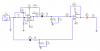
Hi. I'm currently in the process of designing a tunable notch filter for frequencies between around 2kHz to 15Khz. The notch filter is tuned by adjusting resistors R2 and R3. The device will need to 'switch on' an LED when the notch frequency is being presented at the input. I chose to implement the LED activation mechanism by using a schmitt trigger that would 'compare' the output voltage of the filter to the output voltage of the input signal, upon passing them both through a basic rectifier/smoothing section.
I'm using an Op-Amp for the schmitt trigger. What i'm having trouble with is configuring the schmitt trigger's ON and OFF hysteresis limits. Essentially, when the voltage difference at the inputs equals roughly 2.6V, i want the schmitt trigger to go 'negative rail'. When the difference at the inputs equals 3.8V i want it to go 'positive rail'. How can i go about doing that? Please take a look at the circuit diagram for opinions.
Thanks alot.