Electro Tech is an online community (with over 170,000 members) who enjoy talking about and building electronic circuits, projects and gadgets. To participate you need to register. Registration is free. Click here to register now.
Welcome to our site! Electro Tech is an online community (with over 170,000 members) who enjoy talking about and building electronic circuits, projects and gadgets. To participate you need to register. Registration is free. Click here to register now.
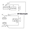
Your top circuit shows the input signal has a positive polarity so a polarized capacitor can be used.
Your bottom circuit shows that both inputs have the same polarity and voltage so no capacitor is needed.
Your bottom circuit shows a high frequency to the top wire of the speaker and a low frequency to the bottom wire of the speaker. It reduces the total power or requires 2 power amplifiers to do that. You could use just one power amplifier to drive one wire of the speaker if the signals are mixed together ahead of the amplifier.
About the duplicate threads, The internet did not work good the first time and I did not know it will show up.
The top circuit, I was wondering if the speaker coil would store a charge and release it into the cap, charging it backwards. Ido not know if it canhappen, so I wanted to ask.
The second circuit, the 2 signals have the same polarity, but they are iverted and the reference voltages are different.
No. The inductance of a speaker is very low so it is a poor generator.
The top circuit shows a DC voltage across the capacitor. The speaker end of the capacitor has 0V so its signal swings positive and negative equally.
The second circuit, the 2 signals have the same polarity, but they are inverted and the reference voltages are different.
I think the amplifier is a bridged amplifier like car radios have. The two signals have the same average DC voltage so coupling capacitors are not needed.
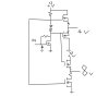
For your upper transistors, you forgot that the gate voltage of a Mosfet must be 5V to 10V higher than its source voltage. So it needs a high supply voltage, it will heat a lot and its output power will be low. Its distortion is high because there isn't negative feedback around the output.
The bottom transistors will be a dead short across the power supply.
An extremely simple amplifier can be made with 3 transistors like this. Its output power is also low. Its distortion is also high because it is too simple.
This site uses cookies to help personalise content, tailor your experience and to keep you logged in if you register.
By continuing to use this site, you are consenting to our use of cookies.