Continue to Site

Welcome to our site!

Electro Tech is an online community (with over 170,000 members) who enjoy talking about and building electronic circuits, projects and gadgets. To participate you need to register. Registration is free. Click here to register now.

  • Welcome to our site! Electro Tech is an online community (with over 170,000 members) who enjoy talking about and building electronic circuits, projects and gadgets. To participate you need to register. Registration is free. Click here to register now.

Old School EDM

Status
Not open for further replies.

jnnewton

Member
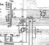
Does anyone know of a better, smaller or easier way to do what this circuit is doing. It is used to control the current in an edm, but is old and parts are hard to come by. The idea is to vary the transformer output (TR4) to cause a change in the input side of the scr. this then causes a change in the current in the upper loop of the diagram.

Thanks.
 

Attachments

  • EDM_Current_Control_A.jpg
    EDM_Current_Control_A.jpg
    609.1 KB · Views: 259
I was thinking that with the transistor technology available now, there might be a better way, this thing was built 60 years ago by a company that is no longer in business. Any Ideas?
 
A better diagram showing the full circuit would help. Parts appear to be cut off. Also show us clearly where all those numbered terminals go to.
 
I am also interested in EDM.

A fellow forum member reffered me to this yahoo group about the subject.
**broken link removed**

I don't think there are any circuit diagrams there, but there is a book put out by lindsey publications that explains how to build a home made setup, including the power supply. I have not got around to buying the book yet, but from what I gather, it seems to be the bible of the EDM hobbiest.

Googling has not turned up much free information on the subject for me.
 
Output from D2 goes to the wire and the table, ct1 goes to another circuit to control the feed rate, this will be replaced with a servo system and the inputs to the multitap transformer com from the 240V line, providing the input to the high current loop. I did not want to include any more, because everything else will just confuse the subject, it is a servo system of some sort that will be completely replaced anyway and the diagram of that system is very hard to read, and will not be used any way.
 
Status
Not open for further replies.

New Articles From Microcontroller Tips

Back
Top