Continue to Site

Welcome to our site!

Electro Tech is an online community (with over 170,000 members) who enjoy talking about and building electronic circuits, projects and gadgets. To participate you need to register. Registration is free. Click here to register now.

  • Welcome to our site! Electro Tech is an online community (with over 170,000 members) who enjoy talking about and building electronic circuits, projects and gadgets. To participate you need to register. Registration is free. Click here to register now.

On board comparator, STM32L073....input bias current?

Flyback

Well-Known Member
Hi,
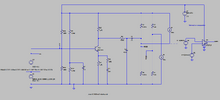
Do you believe that the attached LTspice simulation is the best way to analyse the effects of the input bias current in one of the comparators inside the STM32L073 (48 pin) microcontroller?

STM32L073 datasheet
https://www.st.com/en/microcontrollers-microprocessors/stm32l073rz.html

I believe the input bias current to the comparator input is +/-50nA (Pg 102 of datasheet)?
 

Attachments

  • COMPARATOR input bias current.asc
    16.3 KB · Views: 12
  • Comparator input bias current analysis.png
    Comparator input bias current analysis.png
    49.9 KB · Views: 18
That sim circuit looks okay.
To reduce the voltage offset due to the bias current, you could reduce the values of R20 and R21.
 
Thanks, thats a good idea....of course, the best we would do is reduce the voltage down by 60mV max....which is an improvement...but not great for us.
In fact, i am wondering why 50nA is taken as the comparator input bis current?.......the datasheet says that this is the Digital I/O input bias current, whereas a comparator input is an analog input?....and the datasheet simply doesnt state the input bias current?

I wrote to st.com forum and they just said they wouldnt answer but would contact me directly but they never did....so this sounds ominous.....it suggests that the datashet doesnt state the comparator input bias current.?...otherwise they would have said so?
 
I wrote to st.com forum and they just said they wouldnt answer but would contact me directly but they never did....so this sounds ominous.....it suggests that the datashet doesnt state the comparator input bias current.?...otherwise they would have said so?
There are details that most IC manufacturers are willing to share under NDA - if they think you might buy enough chips to make it worth their effort. Either (1) Once they did some digging, they realized you or your company are not big enough to bother with, or (2) your request hasn't made it to the top of somebody's to-do list yet.

Sometimes, publishing details tells their competitors exactly how a problem was solved - so they don't.

Sometimes, publishing details makes users think a value is a specification instead of just a likely value. Since they don't want to get into problems with any customer, they might make you sign a document that you understand the difference between a likely value and a specification.
 
Is comparator switch C type or true analog in that part ?
Sorry i dont know, datasheet doesnt say. I please request anyone to tell of the answer.?

of course, the best we would do is reduce the voltage down by 60mV max.
Why is that?
Thanks, because bias current is only +/-50nA.

BTW, Do you know if this comparator input bias current is more likely to be coming into the comparator's input pin or out of it?
 
Hi,
The attached comparator circuit takes in some pulsing and turns it into a rail to rail pulsing.
(LTspice and PNG attached)
However, when no pulses come, the signals at the input to the comparator are just 100mV apart.
Also, it is the comparator inside the STM32L073 microcontroller, which has unspecified input bias current,
which may be higher than the 50nA shown here.
Also, the input divider resistances are MegOhm+ and could vary with moisture/dirt ingress.
Would you say this is a reliable design.?
Academically speaking it works, but its shoddy and has no need to be like this.
The circuitry could be easily changed to make the pulsing be rail to rail to the comparator input for example.

Would you go forward with this?....specially since input bias current of the comparator is unknown and may be
significantly higher than the 50nA shown and result in those inputs being even closer in voltage when no pulsing?
 

Attachments

  • comparator unusual.png
    comparator unusual.png
    50.7 KB · Views: 5
  • COMPARATOR UNUSUAL.asc
    5.3 KB · Views: 3

Latest threads

New Articles From Microcontroller Tips

Back
Top