Hello, I have an output where I want to output a pwm signal (1.3kHz, 0-5V). I also would like to use a optoisolator on this output. the signal is generated via a **broken link removed**
**broken link removed**
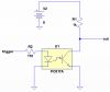
I have a good signal coming off the microcontroller, but have tried varying the base resistor value and the pull-down to get a good output, but the problems are:
if there is no pulldown, the output sits at around 5 V. if the pulldown is as it is, the signal still only swings from around .3 V to 2.4V.
I do not have a good idea of how to fix this. Any suggestions?
**broken link removed**
I have a good signal coming off the microcontroller, but have tried varying the base resistor value and the pull-down to get a good output, but the problems are:
if there is no pulldown, the output sits at around 5 V. if the pulldown is as it is, the signal still only swings from around .3 V to 2.4V.
I do not have a good idea of how to fix this. Any suggestions?