Continue to Site

Welcome to our site!

Electro Tech is an online community (with over 170,000 members) who enjoy talking about and building electronic circuits, projects and gadgets. To participate you need to register. Registration is free. Click here to register now.

  • Welcome to our site! Electro Tech is an online community (with over 170,000 members) who enjoy talking about and building electronic circuits, projects and gadgets. To participate you need to register. Registration is free. Click here to register now.

PCB check

Status
Not open for further replies.

Rocketman

New Member
Hi all,

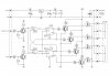
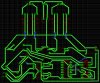
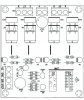
I just finished a pcb design and was wondering if somebody could take a look and point to some errors. I have the original layout as well, but took the liberty of making few adjustments (both are not the best solution). Also the transistors Q7, Q8, Q9 and Q10 don't have markings for the values. Is it somehow possible to know what type they are and their values? Thanks.
 

Attachments

  • Schematic.jpg
    Schematic.jpg
    242.6 KB · Views: 150
  • Board.jpg
    Board.jpg
    1.3 MB · Views: 143
  • Board Layout.jpg
    Board Layout.jpg
    106.5 KB · Views: 136
Maybe larger traces up around the fet's and the motor connections, a more direct connection from the filter cap to the motor connectors or maybe 2 filter caps, 1 near each connector. I would try to have a ground plane in this area, and also some ground plane separating the fets from the low power section of the circuit. The ground trace that runs under the 4 blue jumpers should be made a ground plane and extended up to where the fets connect to it, so you have short ground connections. I would add a jumper in the blue traces in case I later needed to add a small value resistor or ferrite bead in series with the gate.
 
Last edited:
Status
Not open for further replies.

Latest threads

New Articles From Microcontroller Tips

Back
Top