Continue to Site

Welcome to our site!

Electro Tech is an online community (with over 170,000 members) who enjoy talking about and building electronic circuits, projects and gadgets. To participate you need to register. Registration is free. Click here to register now.

  • Welcome to our site! Electro Tech is an online community (with over 170,000 members) who enjoy talking about and building electronic circuits, projects and gadgets. To participate you need to register. Registration is free. Click here to register now.

Peak Rectifier Problem

Status
Not open for further replies.

xmat

New Member
Hello.

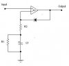
I have a signal inserted into a peak rectifier circuit.
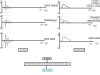
(see graph)

The following problem occurs (described graphically in graph):

Due to the fact that

the peak rectifier takes into account (in order to rectify) only the positive varying parts of AC signals, some important information is lost because some of the signals have their "main" peak in the negative varying area..

So, my question is:
Can anyone suggest a peak rectifier circuit that takes into account poth parts (positive and negative values) of an AC signal??Cause I am a little lost in that one...Please help.
 

Attachments

  • peak_rectifier_circuit.jpg
    peak_rectifier_circuit.jpg
    12.4 KB · Views: 543
  • peak_rectifier_problem.jpg
    peak_rectifier_problem.jpg
    44.5 KB · Views: 557
Try using a fullwave rectifer circuit, most VU and PPM meters use them, this uses both sides of the waveform.

Also, you shouldn't post diagrams as JPG, they are too large and too poor a quality, if you post them as GIF you get 100% quality and a much smaller filesize. JPG is for photographs, and is useless for diagrams.
 
Nigel Goodwin said:
Try using a fullwave rectifer circuit, most VU and PPM meters use them, this uses both sides of the waveform.

Also, you shouldn't post diagrams as JPG, they are too large and too poor a quality, if you post them as GIF you get 100% quality and a much smaller filesize. JPG is for photographs, and is useless for diagrams.

Sorry about the JPG thing, did not know about that.Thanx for telling me.

About your answer:

An absolute value converter rectifies BOTH sides of the signal, I want to find a way to rectify only ONE side

in relation to which side has the largest peak value..

So, if I have case A then the peak rectifier rectifies only the positive side of the signal, while if I have case B the PR rectifies only the negative side of the signal..

Is there a way to do that??
Maybe with 2 rectifiers and a "switching" way to flip between them?

Hope someone can help,

thanx in advance,

xmat.
 
Measuring the rate of change of a signal that is peak rectified...To have an (extra) parameter in case I want to restore the signal to its initial state...Kind of experimental thing..

U see, rectifying only to positive values while the "main/large" peak value is on the negative side actually gives a false indication to restore the PRied signal to the pre-PRied state.
Due to the absence of the negative peak on the PR, the "system" things that there are 2 signals instead of one.

Ok?

xmat.
 
Having read through this thread several times, I have not the faintest idea what xmat is really trying to do!

JimB
 
JimB said:
Having read through this thread several times, I have not the faintest idea what xmat is really trying to do!

No, neither have I?.

Presumably he's trying to achieve something, so how about telling us what it is? - most of these vague questions usually turn out to asking totally the wrong thing!.
 
xmat said:
Nigel Goodwin said:
Try using a fullwave rectifer circuit, most VU and PPM meters use them, this uses both sides of the waveform.

Also, you shouldn't post diagrams as JPG, they are too large and too poor a quality, if you post them as GIF you get 100% quality and a much smaller filesize. JPG is for photographs, and is useless for diagrams.

Sorry about the JPG thing, did not know about that.Thanx for telling me.

About your answer:

An absolute value converter rectifies BOTH sides of the signal, I want to find a way to rectify only ONE side


in relation to which side has the largest peak value..

So, if I have case A then the peak rectifier rectifies only the positive side of the signal, while if I have case B the PR rectifies only the negative side of the signal..

Is there a way to do that??
Maybe with 2 rectifiers and a "switching" way to flip between them?

Hope someone can help,

thanx in advance,

xmat.
If you use a FW rectifier, it will automatically store the highest peak, whether positive or negative. If you want to know whether it was positive or negative - that can be done, but you didn't say that.
BTW, the output from your schematic should be on the cathode of the diode, unless you are looking for a quasi-digital signal, which is what you will get from the anode.
 
Ron H said:
xmat said:
Nigel Goodwin said:
Try using a fullwave rectifer circuit, most VU and PPM meters use them, this uses both sides of the waveform.

Also, you shouldn't post diagrams as JPG, they are too large and too poor a quality, if you post them as GIF you get 100% quality and a much smaller filesize. JPG is for photographs, and is useless for diagrams.

Sorry about the JPG thing, did not know about that.Thanx for telling me.

About your answer:

An absolute value converter rectifies BOTH sides of the signal, I want to find a way to rectify only ONE side


in relation to which side has the largest peak value..

So, if I have case A then the peak rectifier rectifies only the positive side of the signal, while if I have case B the PR rectifies only the negative side of the signal..

Is there a way to do that??
Maybe with 2 rectifiers and a "switching" way to flip between them?

Hope someone can help,

thanx in advance,

xmat.
If you use a FW rectifier, it will automatically store the highest peak, whether positive or negative. If you want to know whether it was positive or negative - that can be done, but you didn't say that.
BTW, the output from your schematic should be on the cathode of the diode, unless you are looking for a quasi-digital signal, which is what you will get from the anode.

Yeap, u are damn right about the output point...My mistake.

Ok, here is what I am trying to do:

A signal passes through a peak rectifier.

All I want is to "restore" some parts/info of the initial signal, like for instance
the TIME of occurrence of the highest-value peak, as well as "decide"
whether that peak occurs during positive vs negative values..(How can I do that?You said it can be done..)

Looking more thoroughly into an AVC circuit, I am thinking that it may be suitable enough...So sorry if I caused to all of you any frustration.

Thanx a lot.

xmat.
 
Status
Not open for further replies.

Latest threads

New Articles From Microcontroller Tips

Back
Top