Hi,
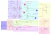
I've attached a pic of the final schematic, If you could please check and see if i've got it right, i've broken it down into coloured block to help, the "connection" points will go to a display board where it will be displayed on 3 different Voltmeters.
The threshold op-amps have a hysteresis resisters for chatter free switching.
The outputs from the pH circuits go to a AND logic to act as a safe gaurd, ensuring the tank pH is above a set limit for the relay to opperate.
Component values not shown.
PLEASE advise if I have made any error with the schematic.
Thanks in advance!