Hi all
As you can see i'm a newbie to the site, I'm got a basic grounding of electronics, enough to survive")
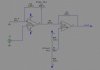
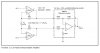
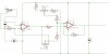
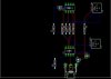
I'm wanting to connect a glass pH probe to my Siemens PLC that runs my marine reef fish tank, it accepts 0-10v.
Found the following schematic on the net, was just about to build it but a fellow reefer said that the probe would pick up interference from the pump, lights, ETC.
what you think, and if you suspect that it will be a problem, how / what should I do to fix it.
Thanks in advance.
As you can see i'm a newbie to the site, I'm got a basic grounding of electronics, enough to survive
I'm wanting to connect a glass pH probe to my Siemens PLC that runs my marine reef fish tank, it accepts 0-10v.
Found the following schematic on the net, was just about to build it but a fellow reefer said that the probe would pick up interference from the pump, lights, ETC.
what you think, and if you suspect that it will be a problem, how / what should I do to fix it.
Thanks in advance.