Continue to Site

Welcome to our site!

Electro Tech is an online community (with over 170,000 members) who enjoy talking about and building electronic circuits, projects and gadgets. To participate you need to register. Registration is free. Click here to register now.

  • Welcome to our site! Electro Tech is an online community (with over 170,000 members) who enjoy talking about and building electronic circuits, projects and gadgets. To participate you need to register. Registration is free. Click here to register now.

PIC 16F877A not working in circuit

Status
Not open for further replies.

sonar_abhi

New Member
Hello Guys,

I am making a simple program to test the pcb I designed.

The program is to turn on a led at PORTC.F3. The PIC16f877A works fine in the development board but it wont work in the actual pcb. I have checked the connections and they seem to be fine.

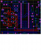
I dont know what is wrong. I am posting a snapshot of the PCB. Please help.
 

Attachments

  • PIC PCB Snap.png
    PIC PCB Snap.png
    61.3 KB · Views: 350
Could you post your schematic please?
 
The crystal should be much closer to the oscillator pins (13 and 14). Long leads add inductance and resistance to the circuit, reducing the quality of the clock signal.
Where is your decoupling capacitor? You should have one as close to the PIC as possible connected between VDD and VSS.

What is PORTC.F3? Do you mean RC3? You don't seem to have anything connected to RC3.
 
Thanks DerStrom8,

I am sorry but I am just an amateur at board design. I just went ahead with the general schematic to pcb conversion. How can I rectify the error now? And what should be the value of the decoupling capacitor?

Sorry if I am coming across as a noob.
 
Your schematic shows 22uF capacitors on the crystal, they should (MUST!) be 22pF.

Decoupling capacitors aren't critical, 0.1uF would do, as would 1uF, 10uF etc.

However, PIC's are VERY, VERY tolerant of having none at all - and while I wouldn't advise that, it's most probably not causing your problem.

If you've used 22uF on the crystal though, that WOULD stop it running.
 
I am sorry, I didnt rectify the string name. The crystal capacitors are 22pF. I have used 22pF capacitors, just forgot to update the string name in the schematic.

The program works perfectly on the Proteus simulator and also on the development board but it wont work on the circuit
 
There should be a capacitor from Vcc to Vdd at the micro. Very close to the pins.
Pins 11-12 and 31-32 Solder these caps on the back of the board and see if that helps.

Look at the development board and see what is different!
 
Hello Guys, I rebuilt the circuit (just for the pic and oscillator) on a vero board and connected it to the original board and it is working fine now. Didn't add any decoupling caps or ground plane yet it is happily working on the vero board and even on the breadboard. What was the original circuit's problem, beats me. Still will definately take care of adding the decoupling capacitors and ground plane while designing the pcb next time around.

Thanks a lot for everybody's help
 
your schematic is not complete. The bottom half is missing. I see no resemblance between the schematic and the partial pic of the PCboard. No leds etc.
One thing I see that you need to do is avoid 90 degree bends in traces.
You should find out why the pcboard does not work as desired.
 
There's a lot wrong with the schematic He dosen't show both VDD tied together and VSS are not too.
 
There's a lot wrong with the schematic He dosen't show both VDD tied together and VSS are not too.

Good catch! Both Vdd pins need to be connected to each other, as do both Vss pins. Can't believe I missed that!
 
Status
Not open for further replies.
Back
Top