Continue to Site

Welcome to our site!

Electro Tech is an online community (with over 170,000 members) who enjoy talking about and building electronic circuits, projects and gadgets. To participate you need to register. Registration is free. Click here to register now.

  • Welcome to our site! Electro Tech is an online community (with over 170,000 members) who enjoy talking about and building electronic circuits, projects and gadgets. To participate you need to register. Registration is free. Click here to register now.

PIC + Cny70

Status
Not open for further replies.

moonstreat

New Member
good ..
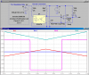
I've got a serious problem, I assembled the following schedule:

**broken link removed**

Uploaded with ImageShack.us

I am after the test did not work in my PIC16F876A because there its output voltage is too low, sometimes does not reach the 2V,

Somebody help me?
 
Last edited:
The LM358 is a pretty bad op-amp, especially when you run it off a single +5V Supply! When you ask its output pin to source more than a couple of mA, it will only pull the output to about 2.5V.

It is better at sinking current than sourcing current. It will pull the output pin to ~100 mV when sinking 10mA. I suggest you reverse the inverting and non-inverting inputs, and connect the LED and its current limiting resistor between the output pin and the +5V supply. Or buy a modern rail-to-rail op-amp which is capable of sourcing and sinking > 20mA.
 
Last edited:
Deleted message.
 
Last edited:
Hi moonstreat,

try this one.

Boncuk
 

Attachments

  • CNY70.gif
    CNY70.gif
    10.4 KB · Views: 8,612
you can post me a circuit that works? I do not know what to do this

Here is how I would do it. I didn't have a sim model of your exact opto coupler, so you may have to optimize R20 and R40 for the specific one you are using. To simulate some variation in the light reaching the photo-transistor, I vary the current in R20. I have turned the comparator upside down to take advantage of its current sinking capability. I have also added some positive feedback R1 to prevent chattering (oscillation near the trip point).
 

Attachments

  • DF14.png
    DF14.png
    40.7 KB · Views: 893
Last edited:
Status
Not open for further replies.

New Articles From Microcontroller Tips

Back
Top