Continue to Site

Welcome to our site!

Electro Tech is an online community (with over 170,000 members) who enjoy talking about and building electronic circuits, projects and gadgets. To participate you need to register. Registration is free. Click here to register now.

  • Welcome to our site! Electro Tech is an online community (with over 170,000 members) who enjoy talking about and building electronic circuits, projects and gadgets. To participate you need to register. Registration is free. Click here to register now.

PIC16F877A sub circuits

Status
Not open for further replies.

eleceyes

New Member
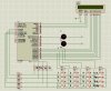
I do programming on PIC16F877A so it can output pulses with cycle specified to make the lamp on and off, I simulate and it runs as I wish.
Now I have to design that circuit with real devices, I know if I design it like what I draw in Proteus software, it will not run, what circuits that I need more to have it operate ?
Thank you !
 

Attachments

  • keypad.JPG
    keypad.JPG
    124 KB · Views: 326
Thanks for your quick reply.
So I have to connect PIC pin via a resistor before connect to LED (uhm ... not lamp)
Oscillator 4Mhz
About power supply circuit, that is one I am wondering, what it looks like, include which components ?
Thanks !
 
Hi,
Nigel meant the supply voltage to the PIC. You're using Proteus to do the simulation, so you don't need to do so. There is no Vdd and Vss for you too, as I know. For the rest, check his tutorial.
 
Status
Not open for further replies.

Latest threads

New Articles From Microcontroller Tips

Back
Top