Continue to Site

Welcome to our site!

Electro Tech is an online community (with over 170,000 members) who enjoy talking about and building electronic circuits, projects and gadgets. To participate you need to register. Registration is free. Click here to register now.

  • Welcome to our site! Electro Tech is an online community (with over 170,000 members) who enjoy talking about and building electronic circuits, projects and gadgets. To participate you need to register. Registration is free. Click here to register now.

PIC18F4550 running on 20MHz?

Status
Not open for further replies.

MrNobody

New Member
Hi,
I'm planning to do PWM and Timer2 with USB feature using PIC18F4550 with crystal of 20MHz.

What I intend to do is to have both PWM and Timer2 interrupt running on 20MHz as in FOSC = 20 MHz.

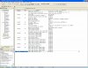
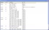
Attached is the print screen of my settings in configuration bits.

To test whether the code is running at 20MHz or not, i program a simple code to blink the LED ON for 1 second and then OFF for another second and i measure its time by using stopwatch. What i found is the code is running slower compared to the stopwatch.

Below is how i did the blinking code. I put it in a while loop so that the PIC will do nothing else except blinking the LED.

Code:
// I'm using 20MHz crystal oscillator.
void main(void)
{
    InitializeSystem();
    while(1)
    {
        USBTasks();         // USB Tasks
        ProcessIO();        // See user\user.c & .h
        while (1)
        {
                PORTD = 0xFF;	
		Delay10KTCYx(200);
		Delay10KTCYx(200);
		Delay10KTCYx(100);
		PORTD = 0x00;
		Delay10KTCYx(200);
		Delay10KTCYx(200);
		Delay10KTCYx(100); 
		}
    }//end while
}//end main

The reason why i did the above testing is to ensure that the PIC is indeed running at 20MHz so that when I do PWM and Timer2, I can use FOSC = 20MHz for the calculation. However, it seems that the PIC is running abit slower than 20MHz and because of that, I'm afraid when I do the PWM and Timer2, the result will be off.. Can somebody pls advice..
Thanks.
 

Attachments

  • Picture_01.jpg
    Picture_01.jpg
    195.7 KB · Views: 787
Hi, i would disable the brown out detection,

and since you are using the crazy USB framework from microchip you should do as they say and place all you code inside the User.c/.h because you are using a framework not just some functions.
Also, i find strange that your pic is running that while you placed because the ProcessIO has a loop at some point, to keep processing USB requests and your user code...

I'm new to USB with PICs, i have posted a thread about the USB function on this pic, search for it, it has some links to some projects that exclude the microchip framework and use a simpler set of functions.

In my case the PIC initiates and when i enable the USB module my windows detects a USB device but it can't get the vendor ID from the PIC, don't know why yet...


Well, i hope this helps, somehow...
 
Last edited:
mvs sarma:
Yes, I did try the stopwatch and it indicates that instead of 1s, it takes about 1.2s which is about the same as the actual stopwatch.
Would it be safe to say that the extra 0.2s is the time it requires to call those functions and not because of the PIC not running on 20MHz..? If it is safe then if i do Timer2, will the result be accurate..?

TiagoSilva:
I place the blinking code in "void main(void)" function because i don't want any 'interruption' while i test the blinking of LED. At this point i don't need the USB feature yet. My whole idea is just to see how fast/slow the LED blink and how close/far it is from the 1s intended. However, when I actually do the code later, i will do it in ProcessIO.
BTW, there is an ebook in welcome - gigapedia.com on USB if you want. The title is "Advanced PIC Microcontroller Projects in C: From USB to RTOS with the PIC18F Series" ebook. Its free but you have to register as member. The book uses MikroC compiler tho.

Thanks all.
 
The timing suggest that your chip is running at 16MHz. The only way this can happen is if you have the PLL output divided by 6 as the clock source, but your config has HS selected. Have you tried setting it in source, I never use MPLAB to set the config as I find it confusing.

Mike.
 
The timing suggest that your chip is running at 16MHz. The only way this can happen is if you have the PLL output divided by 6 as the clock source, but your config has HS selected. Have you tried setting it in source, I never use MPLAB to set the config as I find it confusing.

Mike.

Hmm, do i set it at CONFIG1L and CONFIG1H register?
Is the code below correct..? By the way, I would like the FOSC to be 20 MHz and the USB at 96MHz if possible..


Code:
// USB clock source comes from the 96 MHz PLL divided by 2
// Primary oscillator used directly for system clock (no postscaler)
// Divide by 5 (20 MHz oscillator input)
CONFIG1L = 0b00100100;

// Oscillator Switchover mode disabled
// Fail-Safe Clock Monitor disabled
// HS oscillator (HS)
CONFIG1H = 0b00001100;

Thanks.
 
I always use the config directive. You can find a list of parameters in the MPLAB help file - it's so confusing they gave it its own help section.:rolleyes:

I think for your application you want,
Code:
#pragma config WDT = OFF, LVP=OFF 
#pragma config FOSC = HS, PLLDIV = 5, CPUDIV = OSC1_PLL2, USBDIV = 2

Mike.
 
Oh.. thanks..

BTW, when i tried to enter the code below, it gives me compilation error. I also cannot seem to find CONFIG1L and CONFIG1H in PIC18F4550's header file. Just for understanding sake, is there any way to set the PIC registers by writing to it directly..?

Code:
// USB clock source comes from the 96 MHz PLL divided by 2
// Primary oscillator used directly for system clock (no postscaler)
// Divide by 5 (20 MHz oscillator input)
CONFIG1L = 0b00100100;

// Oscillator Switchover mode disabled
// Fail-Safe Clock Monitor disabled
// HS oscillator (HS)
CONFIG1H = 0b00001100;
 
Just for understanding sake, is there any way to set the PIC registers by writing to it directly..?

Not that I am aware of. You can probably do it by using a section but I find it easier to just use the directive.

Mike.
 
Well, did you set the i/o on TRISA ?
You know, they recomend using LATA for output rather than PORTA, yet both work...

If you are not using the USB module why don't you have it commented ?
This pic PLL is suited to generate the USB working frequency...
 
Not that I am aware of. You can probably do it by using a section but I find it easier to just use the directive.

Mike.

Why not using the MPLAB interactive configuration ? it will generate the needed ASM code without having the user writting directly to the config registers... is this what you asked ?
 
TiagoSilva:
MPLAB interactive configuration..?
How do i use that..?
Where can i find it..?
Thanks..

Pommie:
Tried the directive. The result is the same as before.. So i guess the time difference compared to the stopwatch is because of the latency or extra time needed to call the delay function.. Will try timer2 as soon as i can and hope timer2 will give me a more accurate result.
Thanks anyway.
 
Its easy, the page looks like this one (attached), only the bits change to suit the desired pic.
You should find it in this order -> Configure>Configuration Bits

Then you need to enable the MPLAB configuration bits and disable the code ones (if you have any).

Have fun!
 

Attachments

  • ConfigurationBitsWindow.jpg
    ConfigurationBitsWindow.jpg
    190.3 KB · Views: 527
Configuration bits.

Look for the two attachments. Maybe will help.
 

Attachments

  • Config_Bits.h
    3.3 KB · Views: 348
  • PIC18_config_settings.pdf
    3.1 MB · Views: 604
Status
Not open for further replies.

Latest threads

New Articles From Microcontroller Tips

Back
Top