Continue to Site

Welcome to our site!

Electro Tech is an online community (with over 170,000 members) who enjoy talking about and building electronic circuits, projects and gadgets. To participate you need to register. Registration is free. Click here to register now.

  • Welcome to our site! Electro Tech is an online community (with over 170,000 members) who enjoy talking about and building electronic circuits, projects and gadgets. To participate you need to register. Registration is free. Click here to register now.

Please correct me-o/p impedance?

Status
Not open for further replies.

samy555

Member
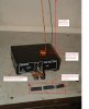
This circuit of the site:
http://www.talkingelectronics.com/projects/27MHz Transmitters/27MHzLinks-1.html
**broken link removed**


I assume that antenna impedance = 50 ohm
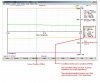
If I ignore the 8-turns ferrite coil, then tried to calculate the antenna impedance that seen looking into point A:
C1 =100pF, C2=150pF and for the inductor L1, I'm supposed 0.5 mm wire diameter according to images, and radius = 5 mm, length = 1 cm, and therefore has inductance approximately = 450 Nano Henry.
**broken link removed**
The 50 ohm antenna appeared to be only 73.7 ohm!!!
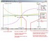
Now we turn to the 4:1 turns ratio transformer:
**broken link removed**
Zs: the total impedance connected to the secondary windings of the transformer
ZP: the total impedance connected to the primary windings of the transformer

My question is: Do I after all these calculations, I can say that the output impedance of the
oscillator = 1.8 Kohm?

Thank you for the patience to read all of my long question
 
My question is: Do I after all these calculations, I can say that the output impedance of the
oscillator = 1.8 Kohm?

No.
What you have done is calculate the load impedance on the oscillator, not its output impedance.
Load Impedance and Output Impedance are not the same thing.


Not only that, but a 30cm long antenna will not have an impedance of 50 ohms at 27Mhz.
Also, given that the other "pole" of the antenna is indefined (just the 0 volt line of the toy transmitter), one could only guess at the impedance which would likely be very low.

JimB
 
Thank you for fast reply
Yes I agree with you on that: Load Impedance and Output Impedance are not the same thing.
I read in "RF secret Design" book somthing like that

A general design rule for the value of inductance used in transformers is that the
inductive reactance at the lowest frequency must be 4 times (4) the impedance
connected to that winding. In the case of the 50- primary of this transformer, the
inductive reactance of the primary winding should be 4  50  200 .

Probably did not ask my question correctly

I know how to design an RF oscillator to work, for example, at 100 MHz frequency
And studied how to use transformers and impedance matching networks (Pi, T and L networks)
But in all cases, you have to know the value of each of these impedances which want to match together
My question specifically: How did the the circuit designer calculate the value of the oscillator output impedance?
Thank you
 
My question specifically: How did the the circuit designer calculate the value of the oscillator output impedance?
My best guess is that he didn't!

You are assuming that the Pi network is for impedance matching, but I think the the designer put it there to act as a low pass filter to attenuate some of the harmonics from the oscillator.

JimB
 
My best guess is that he didn't!

You are assuming that the Pi network is for impedance matching, but I think the the designer put it there to act as a low pass filter to attenuate some of the harmonics from the oscillator.

I would agree, it's almost certainly there just to reduce harmonics and clean up the output.

It's extremely unlikely to be matched to the puny aerial at all, which is far, far too short for 27MHz.
 
I decided to do a bit of follow-up work in the form of a few practical tests on this today.
I wanted to see what the impedance of a 30cm wire antenna would be at 27MHz.

The test I did was done under conditions which were far from ideal, there was no ground plane for the antenna to work against, just the body of the antenna analyser.
So moving the antenna and analyser around on the bench would probably have a big effect on the results, but then this is no worse that what would happen when the original circuit was built, there is no defined ground plane there either.

The pictures in the attachments tell most of the story.
The antenna analyser is an Array Solutions AIM 4170 (Google it), which works in conjunction with some software in a PC.

So, 30cm of wire at 27MHz, in my test setup gave an impedance of 10 Ohms in series with 2pF.

Adding a loading coil of 8 turns on a length of ferrite rod from an old radio antenna changed the impedance to 143 Ohms in series with 8.3pF.
What really surprised me was that this antenna with a loading coil exhibited a resonance at 32.6MHz.
Another turn or two on the coil and it would be resonant at 27MHz.

Coming back to Samys original calculations and ignoring the 8 turn coil and assuming that the antenna impedance would be 50 Ohm, that was not a good assumption.
Allowing for the 8 turn coil with some random piece of ferrite, does give a closer impedance to 50 Ohm, but still quite some way off.

My opinion is that trying to rigorously analyse simple RF circuits such as this is not very helpfull.

JimB
 

Attachments

  • 30cm Antenna test setup.JPG
    30cm Antenna test setup.JPG
    146.6 KB · Views: 218
  • 30cm Antenna no coil.JPG
    30cm Antenna no coil.JPG
    103.4 KB · Views: 197
  • 30cm Antenna with 8 turn coil.JPG
    30cm Antenna with 8 turn coil.JPG
    123.7 KB · Views: 199
I decided to do a bit of follow-up work in the form of a few practical tests on this today.
I wanted to see what the impedance of a 30cm wire antenna would be at 27MHz.

The test I did was done under conditions which were far from ideal, there was no ground plane for the antenna to work against, just the body of the antenna analyser.
So moving the antenna and analyser around on the bench would probably have a big effect on the results, but then this is no worse that what would happen when the original circuit was built, there is no defined ground plane there either.

The pictures in the attachments tell most of the story.
The antenna analyser is an Array Solutions AIM 4170 (Google it), which works in conjunction with some software in a PC.

So, 30cm of wire at 27MHz, in my test setup gave an impedance of 10 Ohms in series with 2pF.

Adding a loading coil of 8 turns on a length of ferrite rod from an old radio antenna changed the impedance to 143 Ohms in series with 8.3pF.
What really surprised me was that this antenna with a loading coil exhibited a resonance at 32.6MHz.
Another turn or two on the coil and it would be resonant at 27MHz.

Coming back to Samys original calculations and ignoring the 8 turn coil and assuming that the antenna impedance would be 50 Ohm, that was not a good assumption.
Allowing for the 8 turn coil with some random piece of ferrite, does give a closer impedance to 50 Ohm, but still quite some way off.

My opinion is that trying to rigorously analyse simple RF circuits such as this is not very helpfull.

JimB

Thank you very very very much
well done

How do I distinguish between circuit operates as a filter and other (of the same elements) works as an impedance matching network?

Are designers who design electronic circuits based on mathematical equations or by trial and error
Or is it that they have computer programs do all the work?

I repeat, deep thanks
Lord bless you from all evil
 
How do I distinguish between circuit operates as a filter and other (of the same elements) works as an impedance matching network?
Generally, they will do both.
A Pi network can be used to perform impedance matching, it will also be a lowpass filter. (Assuming one L and two Cs).
It is common practice to use Pi sections as a pure LPF, where the input and output impedances are the same.


Are designers who design electronic circuits based on mathematical equations or by trial and error
Both! And previous experience.

Or is it that they have computer programs do all the work?
Software is fine if you know what it is doing for you.
Otherwise it is just Garbage In - Garbage Out.

I repeat, deep thanks
You are welcome.

Lord bless you from all evil
I am sorry, but it give me a creepy feeling when people invoke mythical deities to ensure my well being.
A simple thank you is sufficient.

JimB
 
Status
Not open for further replies.

Latest threads

New Articles From Microcontroller Tips

Back
Top