Continue to Site

Welcome to our site!

Electro Tech is an online community (with over 170,000 members) who enjoy talking about and building electronic circuits, projects and gadgets. To participate you need to register. Registration is free. Click here to register now.

  • Welcome to our site! Electro Tech is an online community (with over 170,000 members) who enjoy talking about and building electronic circuits, projects and gadgets. To participate you need to register. Registration is free. Click here to register now.

Please help with bi-directional motor control

Status
Not open for further replies.

GammaRay86

New Member
Hello,

I'm using a PIC with EECP PWM to control the direction and speed of a DC motor. I have the L293DNE to use as an H-Bridge.

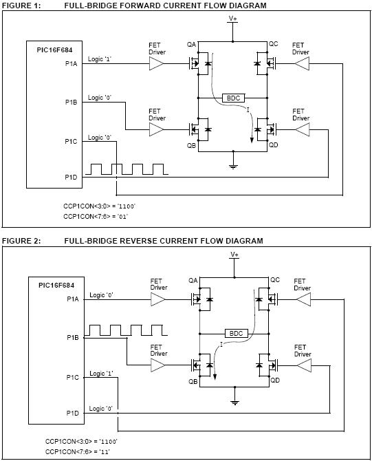
I'm using the full bridge of the PIC PWM as shown below:

28-hbridge.jpg


Below is the L293DNE chip controlling a bi-directional motor:

29-l293dne.jpg


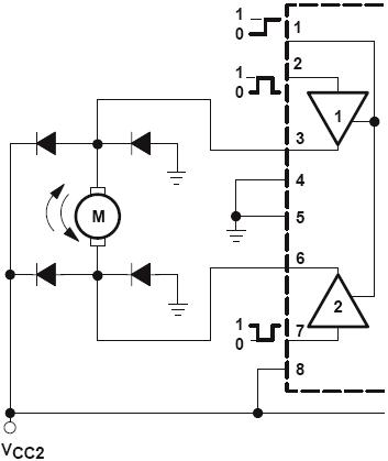
My main question is can I simply connect P1A and P1C to pins 2 and 7 of the L293DNE and connect both P1B and P1D to pin 1 of the L293DNE?

For the forward direction P1D will modulate and for the reverse direction P1B will modulate.

Also, because the outputs are coming from a PIC, do I require those driver FETS show in the first images or are they in the L293DNE already. I would imagine so because the bottom image does not show them.

Is what I am thinking correct? I'd really appreciate any input. Thanks alot!
 
So what I'm doing is right? I want to connect BOTH PWM pins to the 1 enable pin. The other 2 pins, P1A and P1C will connect to the input pins, 2 and 7, of the L293D. Remember I only want to control ONE motor. Do I just disregard the 2nd enable pin, pin 9? I've seen some diagrams where both enable pins were connected together.
 
It's not a great idea. Turning transistors on and off is a lossy, heat-generating process. It's unnecessary to PWM both the high AND low sides of the bridge, and it causes messy switching behavior. Instead, you can use P1A/P1C to select direction and PWM one of the two bottom transistors, or vice versa. Note that you don't need 4 PWM pins to do this. Two are just regular logic outputs.
 
Last edited:
I was always wondering if I needed the 4 pins the full bridge output gave. Would the below half-bridge output configuration work for both controlling speed and direction of a motor?


I can't see why this wouldn't work. If P1A is being modulated while P1B is low, that controls speed in 1 direction, and vice-versa for the other direction. Am I wrong?

Edit: Wait, now that I re-read what you wrote I think you confirmed what I wanted. I'm only using TWO PWM pins, the other two are always just constant low or high, to control direction. If I want forward direction, then I just use figure 1, and if I want reverse direction I used figure 2. In short, I don't think I am doing PWM to BOTH the high and low sides, just 1.

Still though, would what I said above work with the half-bridge output?
 
Last edited:
Technically, what you just drew MAY work... but it's a bad idea. There's no reason to be switching the high AND low side at once. Switching increases losses dramatically. A lot of the time, the transistor which isn't PWM'ed can be a smaller package and/or mounted without a heatsink and the driver is noncritical because the switching time is not an issue.

A lot of high side NMOS drivers pump a capacitor around, which refreshes the capacitor charge when the output is low (off). They CAN'T be given a constant-on duty cycle, the capacitor charge will decay and the gate gets into a partially turned-on state which creates very high heat. This depends on the driver, though. In that type of driver, it's a good argument for making the high side PWM'ed and the lows are only switched when direction changes.

In a simple motor-control H-bridge, you really don't need a motor control PIC. Any PIC with two PWM ports and 2 pins for the directions will drive a basic H-bridge just as well.
 
Last edited:
Isn't what you just described with the 2 PWM pins and 2 pins to control direction the same as what I initially wanted? In figure 1 and 2 that is exactly the pin layout used.

What I mainly am looking for is how to exactly hook up the PIC pins to the H-Bridge pins. The L293D pins are what confuse me since it clearly does not look like a normal H-Bridge but does act as one. Would it be okay for me to attach both PWM pins to the Enable pin (pin 1) of the L293D and attach the logic output pins to control direction to pins 2 and 7 of the L293D? My reasoning is that it shouldn't be a problem for both PWM pins to attach to the Enable pin because for my purposes, only ONE of these will be modulating at a time while the other will be low.
 
Status
Not open for further replies.

Latest threads

New Articles From Microcontroller Tips

Back
Top