Electro Tech is an online community (with over 170,000 members) who enjoy talking about and building electronic circuits, projects and gadgets. To participate you need to register. Registration is free. Click here to register now.
Welcome to our site! Electro Tech is an online community (with over 170,000 members) who enjoy talking about and building electronic circuits, projects and gadgets. To participate you need to register. Registration is free. Click here to register now.
Its possible but the optics and lighting would be a bit difficult to make. The optical mouse chips I've looked at have a sinple 2 channel quadrature output that would be super easy to interface to your system. Getting even lighting and focusing correcly on the sensor at 10cm wil probably be a bit challenging.
Thanks for your reply.
I was afraid that it would be a lil bit too challenging... i had two options on how to make an odometer to this perticular application and this was the one that seemes like most fun to me.
The other option is to use the already existing laser scanner, implement a gyro..and then calculate the approx. speed out of the angels to different reflectors, that's recieved.
Well...was thinking about the..debris factor, maybe it doesnt have to be that high up Ok, let's suppose is doesnt have to be 10 cm above the floor...but not ..stroking it either due to possible variations in the floor .
How high above the ground do you think it would operate on without any major transformations?
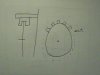
well i was thinking , it has wheels , right ..?
you could easily convert wheel movement into distance..
just hook up an ir transmitter reciever pair to an encoder wheel
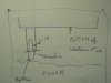
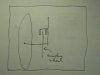
please excuse the crude drawings..
in the third pic labeled pic 2 .. lol
bottom left says "extra wheel" or it did say that till i took the pic...
anyway the idea is to hook another wheel onto the cart bottom with an encoder also on the shaft and the ir reciever attached to the wheel support...
The vehicle already have an odometer that is dependent of a wheel encoder. BUT a SIC-scanner that is used as a detector for obstacles in the vehicle's way needs TWO unrelated speeds when calculating...whatever it needs to calculate in order to minimize probable errors with slips, sharps turns etc etc.
Are you talking about S3000 from SICK? How are you communicating with it? This is sensing device which is often used in safety applications and autonomous vechicles. But... why do you have to send any information such as speed to it? Don't you have to READ information from it and calculate in your controller? (Just curious, I was using them only in safety applications, not on vehicles...)
I'm not too familiar with any "details" yet since I just got the task assigned to me and I havent officially started with it yet, will do that next Monday. Anyway:
Panic Mode:
You may be right that the information about the speed isn't sent to the SICK it self, but to the controller. I may have got some details wrong about the purpose of the individual speed indicators besides the mere "backup-idea", but information about the speed IS used along with the information sent from the SICK.
This site uses cookies to help personalise content, tailor your experience and to keep you logged in if you register.
By continuing to use this site, you are consenting to our use of cookies.