Continue to Site

Welcome to our site!

Electro Tech is an online community (with over 170,000 members) who enjoy talking about and building electronic circuits, projects and gadgets. To participate you need to register. Registration is free. Click here to register now.

  • Welcome to our site! Electro Tech is an online community (with over 170,000 members) who enjoy talking about and building electronic circuits, projects and gadgets. To participate you need to register. Registration is free. Click here to register now.

Power Supply Schematic

Status
Not open for further replies.

123mmm

Member
Hello, I am searching for a good power supply schematic. I tried a few schematics but they were all oscillating.
I am interested in following:
1. To NOT oscillate
2. To have maximum output current 5A
3. To have output voltage range 3-25Vdc
4. To have current limit
5. To be tested.
6. To be simple.

Thanks in advance,
 
Is this for a work-bench type supply?

Post a link to the one that oscillated.
 
This is the supply that oscillated
What frequency? Is it 60, 120hz or 5khz, 1mhz? Just trying to find out if it is ripple or oscillation. (more information)
I might try adding a small capacitor from R to C on the TL431. 0.1uf, 0.01uf, 1nF I do not know with out being there.
 
This event took place a few years ago (2015). On the scope, there appeared a sine wave with Vpp of about a few 10 of milivolts. The period apeared on 0.1us time base.
I don't have any more information about this power supply. At that time I was helped by an engineer and I soldered a few caps but it did not solve the problem. Also, the power supply was making some high frequency sound when powering a load (5A load).
This is why I need a new schematic.
I could use UA723 but it is old and I don't know how long from now it will be manufactured..
 
Does anybody know a good schematic for a power supply with the characteristics from the first message ?
 
Maybe look into the LM338 data sheets. They have examples of 15A adjustable supplies.
The issue at low voltages is the amount heat dissipated by the devices, unless you can reduce the transformer voltages at low settings. To regulate to 25V, you would need at least 28-30V as input under load (should be a lot higher at low loads). At 3V output, your regulators have to dissipate 27Vx5A = 135W !!
I have a bench supply that goes 1-20V in 5V steps, and every 5V step switches the secondary of the transformer to a different voltage as to keep the heat dissipation low.
 
A common trait of many linear power supply designs, including those using an LM317, LM338, etc., is that the current limit is not adjustable. If this is ok for you, then I agree with sagor1 about using a high-current 3-terminal regulator as the core of the circuit.

ak
 
Both the Ua723 or the MC1466L Linear Regulators, make good Power Supplies with Adjustable Current Limits.
 
PWM from BangGood
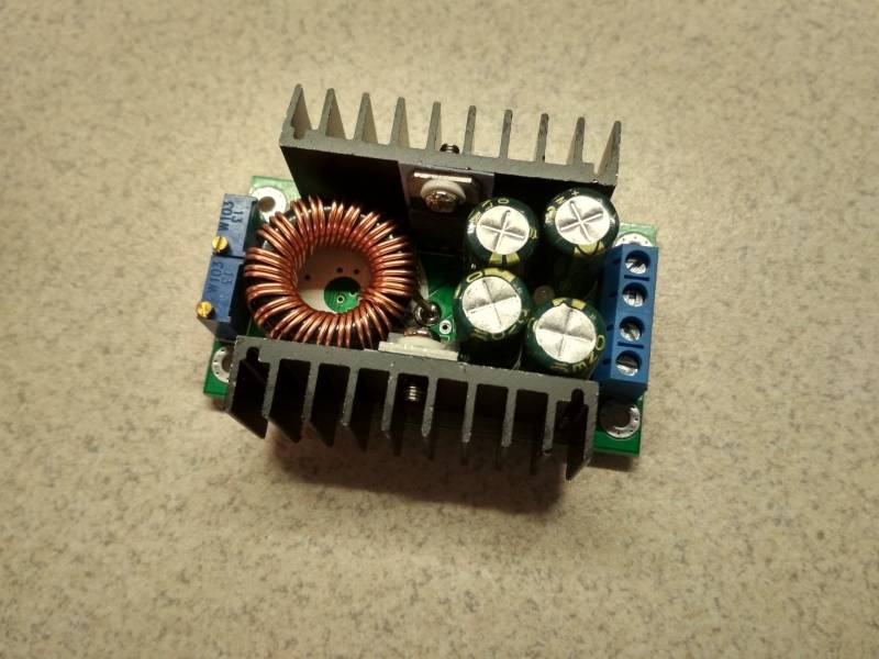
Think about this little board. The input needs to be 40 volts or less DC. There are two pots to set voltage and current limit. The output is 1.25 to 35V or Vin-5V which ever is lessor.
Because it is PWM there should be much less heat.
2018111112571649-969200.jpg

I think this is the same thing but with a fixed 8A current limit.
PWM 8A
I do not know but this might be the schematic for the first supply.
9790ccd0751d4cb49f2ed55e8bdf64bd.png
 
Can someone help with the attached schematic ?
I need to know why it is oscillating and what can be done to eliminate the oscillation ?
It is oscillating when I am powering a device (light bulb for example) which is absorbing about 6-7A. And the voltage on 1N4148 diode is not 0.6V, it is rising to about 4V.
 

Attachments

  • schema-tl431.png
    schema-tl431.png
    78.2 KB · Views: 466
Last edited:
Can someone help with the attached schematic ?
I need to know why it is oscillating and what can be done to eliminate the oscillation ?
It is oscillating when I am powering a device (light bulb for example) which is absorbing about 6-7A. And the voltage on 1N4148 diode is not 0.6V, it is rising to about 4V.

First of all, what is your input voltage? If too low, your regulation will be poor. If too high, you may be overloading certain circuits. Measure the voltage at the +ve end of C5, C6 with no load (minimum load) and full load. Measure the ripple on C5/C6 under full load to see if it is small. Any ripple greater than a few 100mV on input indicates the transformer cannot provide enough current.
The voltage on D1 will vary based on output, as the driver transistor T3 has to be driven more for more current at a given voltage. Oscillations can also happen when the wiring/layout is poorly made, like with long wires or wires crossing over each other. Next time, post a picture of your device setup.
 
I'm not certain but I suspect its an Lm2576 chip.
 
I need to know why it is oscillating and what can be done to eliminate the oscillation ?
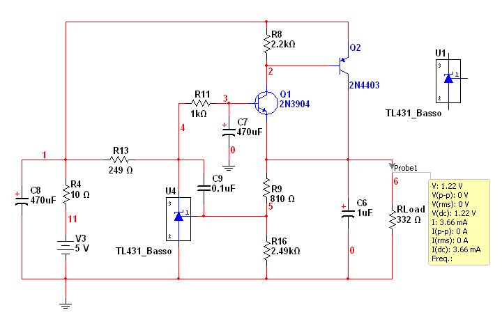
The TL431 is being used as both an error amplifier and 2.5V reference.
images

T1, T2 is a constant current source.
The TL431 has a very large gain. Any time you add a constant current source on top of a amplifier you get much larger gain.
Normally an error amplifier has capacitor(s) from output to input. This reduces the gain at high frequencies, while keeping the high gain at DC.
I might try adding a small capacitor from R to C on the TL431. 0.1uf, 0.01uf, 1nF I do not know with out being there.


1544574813081.png

Here C2 was added to help oscillation.
1544576078822.png

Here a cap is added to the error amplifier. C9 This is what I was talking about in #4.
89748iDA6A07C69D25BE0B
 
I would like to try the attached power supply schematic.
It can be predicted if it will be oscillating or not ?
 

Attachments

  • post-5050-0-28228200-1353606940.jpg
    post-5050-0-28228200-1353606940.jpg
    51.4 KB · Views: 304
Hello, I would like to know if there can be added a fast constant current protection for the attached power supply schematic ?
If yes, can you show me a possible schematic for the fast constant current limit ?

Thank you in advance.
 

Attachments

  • lm324_psu.png
    lm324_psu.png
    59.3 KB · Views: 595
I have a question about connections in power supplies, generally speaking.
If a power supply is oscillating, then is it possible that a bad connection will dampen the oscillations ?
For example, a bad connection in a connector located on the collector of the power transistors.
 
if by bad connection, you mean one that has high resistance that could dampen the oscillations, then, yes it's possible. a bad connection somewhere within the feedback loop can cause oscillation as well. it depends on what component. another thing to keep in mind, is electrolytic capacitors, when they begin to dry out, have high ESR (Equivalent Series Resistance), which reduces the cap's ability to filter out high frequency noise and oscillation. usually, you can't tell by looking at them that electrolytic caps are dried out. sometimes they swell, or pop the top open. but the vast majority of them look ok. when you test them with an ESR meter (which is a 50khz or 100khz oscillator and an attached meter that reads the AC voltage across the capacitor) you can see immediately which ones are good or bad, and in most cases don't even need to remove them from the circuit to test them.

also, having 100mV ripple or noise riding on a 10V output is 1%, which is good enough for most uses. there are times you might want a very quiet rail voltage, but for most stuff, 1% is ok.
 
Status
Not open for further replies.

Latest threads

New Articles From Microcontroller Tips

Back
Top