yngndrw
New Member
Hi,
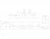
Well there are loads of current limiting adjustable regulator IC's out there, but using one of them is useless if you want to actually learn something. With that in mind, I set out making my own power supply using the (Not so) trusty simulator Livewire.
So here it is. The values are not worked out or anything, and it's not been simulated properly because Livewire seems to like throwing a fit whenever possible.
Features:
*Adjustable from about 0.7V right upto around 26V
*Max current is around 4A according to Livewire, before the voltage drops too much. Oh course, Livewire could be totally wrong.
*Totally incorrect input fuse, because I don't know the max output !
*Adjustable (At build time) "V Droop" via R18. I.e. The output voltage is slightly raised when more current is is drawn, to counter the "droop" when a high load is applied.
*Built in Ammeter via the connection "Current Adjust", 1V = 1A.
*Separate "V Sense" conenction for connecting to the output terminal, to counter the voltage drop due to internal wiring and the current-sense resistors.
*Built in current limiter which (Should) latch the output low and light an LED when the current limit is exceded. Can be reset using the push button "Reset Current Limit".
*Posible to add a current limit meter by adding a Voltmeter to measure the output of VR1 - "Current"", 1V = 1A.
*Probably some other things that I've forgotten.
Anyway, I've attached a low quality picture of it. (Best I could get due to the dimensions.)
I've also attached a .zip file which contains a high res .xps.
.xps (XML Paper Specification) is some kind of Microsoft image format, kind of like a PDF. As far as I know it comes with Windows Vista so anyone with Vista should be able to see that. Link about .xps.
So yea, basically I'd like suggestions, improvements and comments about it. If anyone has a lot of free time and is willing to test it, please let me know how it goes !
Thanks,
-Andrew.
")
