Continue to Site

Welcome to our site!

Electro Tech is an online community (with over 170,000 members) who enjoy talking about and building electronic circuits, projects and gadgets. To participate you need to register. Registration is free. Click here to register now.

  • Welcome to our site! Electro Tech is an online community (with over 170,000 members) who enjoy talking about and building electronic circuits, projects and gadgets. To participate you need to register. Registration is free. Click here to register now.

Problems with dual supply rectifier

Status
Not open for further replies.

ormo

New Member
Hi,

I have a 12-0-12V 250mA transformer in operation from the mains supply.

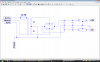
The circuit diagram is attached and I've double checked - it's wired up exactly the same. The capacitors are 50v 2200uF.

3 of the four capacitors heat up within a few seconds and the tops are beginning to bulge slightly. The only one that appears to be ok is the first one between 0 and +15. The output between 0 and +15 is about 16.4V - correct (the boxes represent fixed 15V regulators which haven't been installed yet). The output between 0 and -15 is only about 6.3V.

It may be worth noting that for a few seconds the second capacitor between 0 and +15 was connected in reverse (the positive side on the 0V rail).

Can anyone identify where I might be having a problem?

Thanks,

Mark
 

Attachments

  • Image1.png
    Image1.png
    41.6 KB · Views: 180
This is probably a juvenile mistake, but could the problem be from the fact I am currently running it unloaded?
 
Sounds like the capacitors are either wired up with the incorrect polarity or are faulty. Certainly connecting them in reverse, even momentarily, can cause them to fail.
 
This is probably a juvenile mistake, but could the problem be from the fact I am currently running it unloaded?
Running unloaded will have no effect.
 
I have replaced all 4 capacitors but now only have one each side. The one between 0 and +15 is working fine and the output is about 16-17V. The one between 0 and -15 is still heating up and the output is about 8-9V. I don't understand where the problem could be.
 
Are these low dropout regulators?

If not, a 12V transformer won't do, you need a 15V transformer minimum.

How much current do you plan to draw?

A 250mA transformer restricts you to 175mA.
 
The voltage regulators aren't connected yet, but I've used them from the same transformer before and it all worked so I guess they're suitable
 
Do you have the capacitors on the negative rail connected correctly?
That is, with the + side going to your 'chassis ground' rail, and the - side going to the -15 volt rail?
 
Last edited:
Why did you connect PE (earth) to circuit ground? Earth is only used for mains loads.
 
Posting a schematic which has problems with the polarized caps, and not including cap polarities on the schematic is, well, errmmm,...:eek::rolleyes:
 
1) Check the capacitor polarities and add them to your diagram.
2) Check the capacitor voltage ratings and add them to your diagram.

See you back here soon!!!
 
I would have you also double check for proper diode polarity wiring. The drawing is correct but it sounds like you might have some of the diodes wired wrong and sending AC to the caps which will destroy them. That or caps wired in backwards but thats already been mentioned.

Lefty
 
Last edited:
Status
Not open for further replies.

Latest threads

New Articles From Microcontroller Tips

Back
Top