Continue to Site

Welcome to our site!

Electro Tech is an online community (with over 170,000 members) who enjoy talking about and building electronic circuits, projects and gadgets. To participate you need to register. Registration is free. Click here to register now.

  • Welcome to our site! Electro Tech is an online community (with over 170,000 members) who enjoy talking about and building electronic circuits, projects and gadgets. To participate you need to register. Registration is free. Click here to register now.

produce digital signal, based on a fixed Amp threshold?

Status
Not open for further replies.

settra

Member
Hello forum . i want to build this circuit, and i need some help! :


basically, what i want to do, is this :
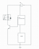
the "LOAD" circuit, will usually draw , lets say 100mA. But some times, it will draw 300-400mA. (this numbers are not exact, but i can make them exact, with current limiters i suppose).
I want the "SENSE" circuit, to detect, when the current is 300mA+ , and only then, produce a signal, so that i can oparate the relay !

Any simple way , that i can make the SENSE circuit?? thanks !!
 

Attachments

  • current sense.png
    current sense.png
    39 KB · Views: 186
Here is a simplistic solution:

352.gif

Plot shows V(out) vs load current at temperatures from 0C (green) to 30C (lt. blue).
It drives a relay with a coil resistance > 100Ω.
Its trip point is ~0.65/R1 Amps.
It is somewhat affected by temperature.
Biggest problem is the peak ~1.5V drop across R1 when load current is 400mA.


Ratchit See Ratch, you worry about minutia; I just use LTSpice and get the job done...
 
Last edited:
cool ! thanks for the quick reply !!
the problem is, that most propably , the resistor coil will be ~60 Ohm (automotive relay)..
will this transistor be able to drive the coil?? ..

the voltage drop at 400mA is not a big problem, becouse the "peak" current, will always be "momentary" , and the "load" arledy works with vRreg at 5v !

But anyway, if i use a smaller, 5W resistor, between 2-3 Ohm, the voltage drop will be even smaller. correct?
thanks again!
 
Last edited:
Here is a version that drives an automotive sugar-cube relay. I added the Darlington to drive the higher current coil. The sim shows the effect of varying R1 through the standard values of 1.2, 1.5, 2.2, and 3.3Ω

352a.gif
 
Here is how to "fine tune" the trip point.

352b.gif
 
hey ! so i am experiancing the following problem :

the relay indeed does not close for small currents
(relay coil is 72ohm btw)
BUT, if the relay closes for some reason (etc , larger current), then after the current is removed, the relay does not de-energize... the voltage on its coil is around 5volts on that time..
any idea what might be causing this?? i used the 2.2ohm R1 !

edit : NVM, the Q1 was propably burned/not working correctly. now everything works! thanks again !
 
Last edited:
...
edit : NVM, the Q1 was propably burned/not working correctly. now everything works! thanks again !
I was going to suggest that Q1 might be bad or leaky. The relay will provide some hysteresis; its release current is less than its pull-in current, but the slope of the red plot in post #4 indicates that the on/off differential should be fairly small...
 
Status
Not open for further replies.

Latest threads

New Articles From Microcontroller Tips

Back
Top