Electro Tech is an online community (with over 170,000 members) who enjoy talking about and building electronic circuits, projects and gadgets. To participate you need to register. Registration is free. Click here to register now.
Welcome to our site! Electro Tech is an online community (with over 170,000 members) who enjoy talking about and building electronic circuits, projects and gadgets. To participate you need to register. Registration is free. Click here to register now.
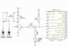
Yes, except I don't like the LED where it is - it will restrict the base current available for the transistor slightly.
What current does your relay take?, as it's 24V the current is probably low? - if it's only 20mA or so, you may be able to connect it directly to RA4?, but check the datasheet, and make sure RA4 will take 24V, this is the advantage of an open-collector output (don't forget the diode across the relay though!).
This site uses cookies to help personalise content, tailor your experience and to keep you logged in if you register.
By continuing to use this site, you are consenting to our use of cookies.