Continue to Site

Welcome to our site!

Electro Tech is an online community (with over 170,000 members) who enjoy talking about and building electronic circuits, projects and gadgets. To participate you need to register. Registration is free. Click here to register now.

  • Welcome to our site! Electro Tech is an online community (with over 170,000 members) who enjoy talking about and building electronic circuits, projects and gadgets. To participate you need to register. Registration is free. Click here to register now.

RADIO's

Status
Not open for further replies.

Dr_Doggy

Well-Known Member
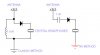
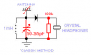
k, so iv been reading about crystal radios, im just wondering based on my filter circuits couse, an inductor in paralel is a highpass filter, another way to do this is with a capacitor in series, so would I be able to drive a crystal radio with dielectrics only, no inductors, providing i used thevenin equivilant inductions???
 
ya, a filter is esentially a pass or reject, where the inductor is a low pass filter, and the cap is the high pass filter, causeing a tuneing to a narrow band
so why cant we instead of useing an inductor in parallel use a thevenin equivilant capacitor in series. Where am I going wrong here?
 
well, can you post a picture of what your circuit would look like? then we can tell you why it should or should not work.
 
note that I didnt bother matching impedance values, however these values can be detirmined with algebra
 

Attachments

  • radioidea.jpg
    radioidea.jpg
    12.1 KB · Views: 139
In the classic method, isn't there also a capacitor from ANT to ground? In your schematic, the detector diode will be given all the high frequency components of the incoming signal. By adding a cap in parallel with the inductor, the detector gets only a band of frequencies.
 
where is the cap?

The “my method” is not going to work well.
The coil needs a capacitor! There must be an LC to resonate.

All coils have some capacitance just like all capacitors have some inductance. My first coil was wound on a toilet paper role. The coil self resonated in the AM band. There was no “capacitor” soldered across the coil. The coil was wound in such a way that it had a large amount of capacitance. Every time two wires get near each other but do not touch it forms a small capacitor. From every turn of wire to the next turn there are “capacitors”.
 
all im really sayin is that in a band-pass filter (parallel) you got your L and C in parallel, or for the same filter type you can stack L and C in series to get the same effects, however in doing this it switches the "roles" that L & C play(highpass-lowpass), so in theory couldn't we take that parallel filter, pull out the L(thats in parallel) and then replace it with a C that is in series to get the same filtering effects?
 
so whats the diffrence,? your feeding in the EM from the antenna then useing iimpedances to filter it down.
 
doggy__ said:
so whats the diffrence,? your feeding in the EM from the antenna then useing iimpedances to filter it down.

They are completely different, a tuned circuit is resonant, and has a magnification factor (Q). It's really fairly basic electronics?, I suggest you get yourself a copy of either the ARRL or RSGB Handbooks - an essential resource for anyone interested in electronics - doesn't have to be a new one, an old edition would be fine.
 
An crystal radio has a tuned circuit, a detector diode and a DC load for the diode.
Yours is missing a couple of them.

You even had a battery, I don't know why.
 

Attachments

  • crystal radio.PNG
    crystal radio.PNG
    16.5 KB · Views: 146
A simple L/C tuned filter gives a simple crystal radio a chance to receive a single specific frequency, it's selectivity is dependent on the Q factor of the L/C tank. If you make the L or C variable you have a chance to receive specific frequencies as you tune through the L/C's frequency range.

Feeding a simple crystal detector with a simple low pass (L) or high pass (C) will make the receiver respond to all frequencies above or below a certain frequency AT THE SAME TIME and makes it pretty useless as a receiver.

However as simple signal strength meter (detector diode driving a sensitive DC meter) normally uses a simple inductor or choke to allow a broadband response to relative near field signal strength it's seeing.

Lefty
 
Status
Not open for further replies.

Latest threads

New Articles From Microcontroller Tips

Back
Top