Continue to Site

Welcome to our site!

Electro Tech is an online community (with over 170,000 members) who enjoy talking about and building electronic circuits, projects and gadgets. To participate you need to register. Registration is free. Click here to register now.

  • Welcome to our site! Electro Tech is an online community (with over 170,000 members) who enjoy talking about and building electronic circuits, projects and gadgets. To participate you need to register. Registration is free. Click here to register now.

Relay energy saver schematic, Need help on the R & C val

Status
Not open for further replies.
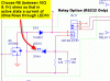
In Elektor March 2006 pg 73 an Energy saver for relays schematic was publised as a design tip. Although it specified a green 20ma LED the other values were a little broad and no theory or calculation data was given.

It would be easy to add this to the schematic and I don't need to use RB3 as a PWM (I use TIMER2 for a 1/256 RTC & display refresh on the Cricket thermostat) so this would be a rev H change.

Any suggestions for the following schematic? C20 & R8?
 

Attachments

  • relaypowersaver.gif
    relaypowersaver.gif
    10.1 KB · Views: 515
If you have a spare PWM channel, using PWM will be simpler and take even less current.

Basically once the relay is latched, you are turning on the transistor and letting coil current rise, then turn off and let the current flow through the diode (which should ideally be a Schottky). Current will decay sort of slowly through a near short like that. So no resistor, caps, or LED and it's quite efficient.
 
I realise the PWM is the most efficent way to run the relay, But PWM uses timer2 and I'm using that as a free running timebase.

Also in my other schematics (Ladybug as an example) I have 6 relays and it would be nice to add the cap to the design. (same relays)
 
Status
Not open for further replies.

Latest threads

New Articles From Microcontroller Tips

Back
Top