Electro Tech is an online community (with over 170,000 members) who enjoy talking about and building electronic circuits, projects and gadgets. To participate you need to register. Registration is free. Click here to register now.
Welcome to our site! Electro Tech is an online community (with over 170,000 members) who enjoy talking about and building electronic circuits, projects and gadgets. To participate you need to register. Registration is free. Click here to register now.
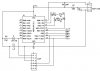
Could you please take a look at the schematic of my robot so far and see if I have missed something or went wrong somewhere. I am a software guy so please be nice
P.S: The open ended resistors go to the motor controller which works well.
It looks fine except for sharing the ICD pins with the motor drive. Doing it this way you will not be able to debug. Why don't you use port A to drive your motor.
Thats a nice point. I think I will do that now. I chose the present pins just beacuse of their positions. I thought it would be easier to fabricate it on a veroboard.
Whoops, you are correct. I am so used to using the 16F88 that I forgot that small point. Maybe you should consider the 88 as having debug facilities is so useful.
Pommie, I also wanted to go with the 88 but it was just not available here. I am planning to move to C on 18 series altogether but still using 16F for the time being just to be able to teach myself how to keep the costs low and how to code in assembly.
BTW, I read in many places that the mclr diode is optional. I dont understad why. If I dont put it, I might fry the TSOP1738 ! or am I missing something.
The diode is optional, what it does is prevent the VPP from putting current on the VDD line.
The TSOP1738 needs a 100ohm and 4.7uF cap on it for proper operation.
I see. Does it mean that even if there is no diode to prevent VPP from putting current on the VDD line, the TSOP will be fine all thanks to the 100ohm and 4.7uF ?
This site uses cookies to help personalise content, tailor your experience and to keep you logged in if you register.
By continuing to use this site, you are consenting to our use of cookies.

")