Continue to Site

Welcome to our site!

Electro Tech is an online community (with over 170,000 members) who enjoy talking about and building electronic circuits, projects and gadgets. To participate you need to register. Registration is free. Click here to register now.

  • Welcome to our site! Electro Tech is an online community (with over 170,000 members) who enjoy talking about and building electronic circuits, projects and gadgets. To participate you need to register. Registration is free. Click here to register now.

Rewire 3 phase 440v to 240v

Status
Not open for further replies.

nathanaelf

New Member
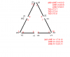
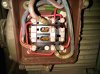
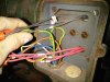
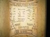
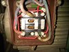
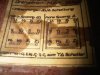
Can anyone tell me the procedure to rewire a 440volt motor to run on 240volts? I have a high leg delta service. There is a diagram on the back of the cover but it does not explain the three red wires in the picture (I penciled them in on the picture of the diagram).

I can see that each coil is wired in series and have read that for low voltage they should be parallel. but I don't know what to do with the red jumpers.
Thanks!
Nate
 

Attachments

  • IMG00044-20101211-1208.jpg
    IMG00044-20101211-1208.jpg
    355.2 KB · Views: 746
  • IMG00046-20101211-1211.jpg
    IMG00046-20101211-1211.jpg
    245 KB · Views: 735
Last edited:
I'll be back with a drawing
P.S. looks like a delta connection
The connection block doesn't match the drawing, but I'm still working on it to make sure I got it right for you.
where are you, USA?
Kinarfi
 

Attachments

  • untitled.PNG
    untitled.PNG
    20 KB · Views: 1,813
Last edited:
LOOKED AT IT FOR A WHILE
it is my bet that each jumper in the picture is 2 jumpers, pull them and put them back on as I have drawn it with the red boxes.
kinarfi
 

Attachments

  • untitled3.jpg
    untitled3.jpg
    349.3 KB · Views: 589
Now I have conveyor motor that needs addressing. It's a 2 speed motor and it's label (what's left of it at least) says 220/440v. there are 6 wires coming out of the motor and all six go to a tumbler switch to change the configuration/speed. The tumbler switch has a thorough schematic on it's cover but doesn't get in to voltage and the motor cover has nothing. I don't see how this motor can run at 2 different voltages and two speeds and all of this can be changed from six wires. Is it possible that it could run at either 220v or 440v without changing the wiring? or are six conductors enough to achieve all of these options?

The picture of the diagram is what's on the inside of the switch cover.
 

Attachments

  • IMG00050-20101215-0822.jpg
    IMG00050-20101215-0822.jpg
    357.2 KB · Views: 582
  • IMG00053-20101215-0825.jpg
    IMG00053-20101215-0825.jpg
    388.7 KB · Views: 615
Looking at the schematic of the switch it is just changing the configuration of the windings from star to delta. With a generator for example if you connect one side of the three windings and the other end of the winding to the out put the join of the windings is the star point. I you take a supply from one of the seperate windings and the star piont you get 240 volt That is how we generate our power in Australia. In fact we use the star piont as the earth. There are a lot of formulea that I used to be able to quote that tells you in a motor if you supply 240V between the star point and the other end of the windings with three phase you will get a rotating magnetic field that passes the windings(bars) of the rotor which induces current which gives the magnetic field of the rotor trying to catch the rotating field and the rest is history.
 
Status
Not open for further replies.

Latest threads

New Articles From Microcontroller Tips

Back
Top