hi all
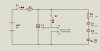
currently doing this simple circuit and needs your thought on it. i.e. if any corrections to be made on the components value/s and whether 2 zener diodes are needed in this circuit (as oppose to only one)?
the idea is to charge the capacitor (up to max d.c voltage) and discharge it (upon the 2nd switch) to the cuvette.
by the way the cuvette is use as a beaker in which to contain cells (human, bacteria, plant, etc) and analyse how cell/s react upon electrical short that passed thru them.
hope you guys may help TIA
ezak