Continue to Site

Welcome to our site!

Electro Tech is an online community (with over 170,000 members) who enjoy talking about and building electronic circuits, projects and gadgets. To participate you need to register. Registration is free. Click here to register now.

  • Welcome to our site! Electro Tech is an online community (with over 170,000 members) who enjoy talking about and building electronic circuits, projects and gadgets. To participate you need to register. Registration is free. Click here to register now.

Simple Resistor Question...

Status
Not open for further replies.

Carpesimia

New Member
Ok, I think this is just a simple resistor question, but I could be wrong.

I'm installing a back-up camera in my truck. Normally, I'd just hook the camera to 12v ignition power, and be done with it. Except this camera has built-in lights to illuminate the area behind you.

That being the case, next plausable thing would be to hook it to the reverse light's power, so it comes on when I put the vehicle in reverse.

This is also well and good. Except I'm never happy with simple. I want the ability to see the rear display while I'm driving. My head unit supports it.

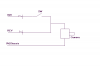
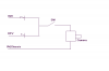
So, what I must do, it seems, is run off of a dual solution. I'll have the camera hooked to the reverse lights, so when I go into reverse it powers on. At the same time, I'm going to install a small toggle in my dashboard so I can manually power the camera on and off while Im driving.

BUT... I dont want to throw power to the reverse lights when I hit the switch, and I dont want to feed the other way in the event the switch is on while I go into reverse.

So, I imagine that I'm going to need some resistors on both sides. One between the camera and the reverse light, and another between the camera and the front switch.

Thats where my supposed knowledge stops. Is it, indeed, resistors I need? If so, how do I determine what size I need? What else do I need to know so I dont just hose my camera and/or my trucks electrical system.

Thanks!

Rich


P.S. - My apologies if I posted this in the wrong forum. After reading the descriptions, this one seemed most appropriate.
 
hi,
From your description, you require 2 power diodes and a switch.

A diode feed from the IGN and a diode feed from the REV. the junction of the two diodes goes to the camera system, via an On/Off switch.

Whats the power requirement of the camera.??

EDIT:

Look at this image.
 

Attachments

  • Image1.png
    Image1.png
    2.6 KB · Views: 142
Last edited:
Ok...here is one option.

Auto:
Power EVERYTHING off of 12 volts from the battery, or 12 volts from where ever. Don't use the activation signal (the reverse lights coming on) as your power source too. Simply use the reverse lights as your activating signal. Hook up your camera and the reverse lights that come with the camera to transistors that connect to your main power source, and connect a wire from the reverse lights (your signal) to the base of the transistor. When the reverse lights on the truck come on, they will sat. the transistor, and activate the camera. The same goes for the lights that came with the camera.

Manual:
Simply run a line that shorts the transistor out of the line with a switch, once you flip the switch, you short out the transistor (not literally short, more appropriately BYPASS), and activate either one, or both, the camera and the camera lights manually.

I can provide a schematic if that will help.

I hope this makes sense.:)


edit: A relay will work also, of you would like to avoid using transistors.
 
Last edited:
hi,
From your description, you require 2 power diodes and a switch.

A diode feed from the IGN and a diode feed from the REV. the junction of the two diodes goes to the camera system, via an On/Off switch.

Whats the power requirement of the camera.??

EDIT:

Look at this image.

Ok, if I understand this, the switch needs to be between all of the power sources. I had planned on using the reverse light lead (in the back of the truck) for my power, so in this case I'd have to find such a lead up front in the dashboard.

As far as power, its 12vdc, whatever the car electrical system has to offer. there is nothing, even in the package, with any more detailed requirements.
 
Ok...here is one option.

Auto:
Power EVERYTHING off of 12 volts from the battery, or 12 volts from where ever. Don't use the activation signal (the reverse lights coming on) as your power source too. Simply use the reverse lights as your activating signal. Hook up your camera and the reverse lights that come with the camera to transistors that connect to your main power source, and connect a wire from the reverse lights (your signal) to the base of the transistor. When the reverse lights on the truck come on, they will sat. the transistor, and activate the camera. The same goes for the lights that came with the camera.

Manual:
Simply run a line that shorts the transistor out of the line with a switch, once you flip the switch, you short out the transistor (not literally short, more appropriately BYPASS), and activate either one, or both, the camera and the camera lights manually.

I can provide a schematic if that will help.

I hope this makes sense.:)


edit: A relay will work also, of you would like to avoid using transistors.


Ah, you just said the magic word to me. Relay. So, I could just have 2 12vdc power leads back there, one coming from the reverse lights and the other just +12v when the key is on, and just have my "switch" hooked to my relay, switching back and forth. Default is by-reverse lights, but I can "override".

The whole issue is that the lights are not on a seperate power lead from the camera. Otherwise I'd just leave the camera on all the time, and just put a switch on the lights, and call it a day.

I dont know that a relay is a better solution, but I do understand how a relay works versus transistors.

My knowledge of electronics is just enough to get me in trouble ;)
 
A variation of Erics circuit to better fulfill your requirements.

1 The camera will be powered whenever reverse is selected.

2 The camera may be powered by the switch when the ignition circuit is live.


In Erics original circuit, the switch had to be closed to power the camera when selecting reverse.

JimB
 

Attachments

  • camera wiring modified.PNG
    camera wiring modified.PNG
    6.5 KB · Views: 146
Status
Not open for further replies.

Latest threads

New Articles From Microcontroller Tips

Back
Top