Continue to Site

Welcome to our site!

Electro Tech is an online community (with over 170,000 members) who enjoy talking about and building electronic circuits, projects and gadgets. To participate you need to register. Registration is free. Click here to register now.

  • Welcome to our site! Electro Tech is an online community (with over 170,000 members) who enjoy talking about and building electronic circuits, projects and gadgets. To participate you need to register. Registration is free. Click here to register now.

Soldenoid problem

Status
Not open for further replies.

vinvin

New Member
Hi pple,
I have one problem.
I am currently working on a vibration or shaking toy.
In the first place, i used a motor with a oval shaped metal,
but i wasn't strong enough or not vibrating vigorously.

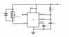
Now i using a soldenoid and i want it to like fire repeatedly like a vibrator.
i have a 12V soldenoid now.. so my question is do it need a driver circuit?
or can i like bulid a square circuit to turn it on and off??
 
You might also consider reversing the polarity. Consider that your load will be inductive and you must protect sensitive components from the inductive spikes that are likely to result.
 
Thanks for the quick reply.
i am quite a newbie to electronics... so how am i suppose to do it?
 
I'd treat the solenoid as a speaker and drive it with an audio amplifier - with an audio generator as input to the amplifier. You want to work with fairly low frequencies - maybe 10 or 20 Hz though higher may work. A TDA2002 is relatively cheap and can drive a load impedance as low as 1.6 ohms. Since you aren't likely to know the impedance of the coil on your solenoid you may want to put a resistor in series with the solenoid - maybe start with 1 ohm - and see what happens. You might ruin an IC or two but again, they are relatively inexpensive. See the TDA2002 datasheet for a circuit.

Please be aware that applying excessive current to the solenoid can ruin it. What I've proposed isn't good design.
 
If this solenoid is going to be forced to pulsate often, you will definitely mush out the bottom of the plunger itself and then it will freeze within the coil. This happens all the time on pinball machines since the coils run off of AC. Placing a diode across the coil terminals lengthens the life of the solenoids but they still demise over time from the continuous slamming of the plunger. Some better designs are using nylon stops to cushion the point of contact at the coil's base. I have removed dozens of solenoid plungers, filed off the mushroomed ends, chamfered them a bit, and then returned them to service. The root of the problem is the steel plungers are made of soft steel.
 
Hi pple,
This is what i came up with.
Please see whether it will possiblely work out.

stevez,
Thanx for the idea i will definitely check out the TDA2002 that u mention.

HiTech,
The soldenoid is go to lift something light up, so as to simulate the vibration of the toy. and its rather going to hit on something soft.
Going with your idea i place a diode parallel to the soldenoid.
 

Attachments

  • HEAR.jpg
    HEAR.jpg
    26.9 KB · Views: 134
Well, it didn't actually work...
yes there is a some sort of turn on and off for the soldenoid...
But it is rather unstable or some sort..
It only works like for 5sec and the stop moving... hiaz..
is there something i forget to connect or?
i also notice that the 555 timer begins to heat up after the soldenoid stop..

Help please...
 
Nigel Goodwin,
power transistor??Err... do u have a part number?
how shld i connect it?
Thanks in advance..
 
Most small to avg. sized solenoids work well off of the TIP series Darlington transistors in the TO-220 style case. Heat sink the transistor. Many of the pinball solenoids were driven by a TIP120 Darlington. Below is a circuit that might work for you. It can operate from 12vDC - 30 vDC and the base or pin 1 is the trigger signal input.
 

Attachments

  • solenoid driver circuit.JPG
    solenoid driver circuit.JPG
    34.3 KB · Views: 125
Last edited:
Thanks HiTech.

Ok with alll the information here i designed this circuit.
Can someone verify for me please?
Cause i wanted something that trigger automatically like a vibrator...

Therefore the previous configuration for the 555 timer is wrong.
I have now config it to Astable operation, to produce a "square wave".

Will this work? If not, can someone help me by drawing the correct circuit?
Really really urgent now.. Thanks in advance..
 

Attachments

  • HEAR.gif
    HEAR.gif
    6.1 KB · Views: 140
I've redrawn your schematic with the necessary corrections.
You currently have your frequency set at 720Hz. I don't think you'll get much vibration at that frequency - just a tone. The 555 datasheet has the equations for frequency and duty cycle.
 

Attachments

  • solenoid driver2.gif
    solenoid driver2.gif
    6.6 KB · Views: 124
one other point - the 555 can sink or source up to 200 mA on it's output pin so depending on the solenoid, it may work ok without a driver.

the package can dissipate quite a bit of power (relatively speaking for a DIL-8) as well. if you set the duty cycle reasonably low, you should be fine on the heat (as long as the current is within the limits).
 
philba said:
one other point - the 555 can sink or source up to 200 mA on it's output pin so depending on the solenoid, it may work ok without a driver.

the package can dissipate quite a bit of power (relatively speaking for a DIL-8) as well. if you set the duty cycle reasonably low, you should be fine on the heat (as long as the current is within the limits).

Yes, even if it can sink 200mA, I don't think it's a good idea.
 
care to explain your reasoning? the data sheet lists it as a feature not a max. I agree that I wouldn't run at 200 mA all the time but for a reasonable duty cycle it will probably be fine. Interestingly, the datasheet (and several other 555 DSs I looked at) don't seem to list a max output current sink or source. the one area I would take a close look at is the output voltage drop at higher currents. probably still within the must operate zone of the solenoid, though.

of course this assumes that the solenoid's draw is <200mA
 
Hi pple,
Thanks for the help.. the circuit is fine now..
Now just have to integrate it... Hopefully everything will be fine.
Will keep u all updated..
Wish me luck.
 
SO, did you end up using the circuit submitted by Ron H?
 
Yes i end up using the circuit by Ron H.
Cos without the power transistor.. the 555 timer get heated up easily..
Thanx Ron the circuit helped me alot...

Well as for the integration.. it some sort failed..
Cos i have to connect to this circuit which supplies the 12V, and it ended up something like loading making the soldenoid not really firing sometimes..
Not sure of the details of the circuit.. but i have more time i will continue to post..

I really got alot of help here.. thanx guys..
 
Last edited:
Status
Not open for further replies.

Latest threads

New Articles From Microcontroller Tips

Back
Top