Continue to Site

Welcome to our site!

Electro Tech is an online community (with over 170,000 members) who enjoy talking about and building electronic circuits, projects and gadgets. To participate you need to register. Registration is free. Click here to register now.

  • Welcome to our site! Electro Tech is an online community (with over 170,000 members) who enjoy talking about and building electronic circuits, projects and gadgets. To participate you need to register. Registration is free. Click here to register now.

Solid-state audio amplifier complexity vs valve/tube

Status
Not open for further replies.

Elerion

Member
This posts aims to get opinions about why solid-state audio amplifier circuits are almost invariably much more complex than valve/tube amplifier circuits.

One could think that, if a good tube circuit is just redone, susbtituting each tube by a transistor (common cathode by a common emitter/source; cathode follower by a emitter/source-follower, and so on), adjusting the bias (obviosuly, much lower voltages, higher currents), the end result should be fine.

But the reality is that even the simplest audio amplifier is much more complex. The input stage is, most times, a non-trivial differential ampliffier (long-tail pair) a current source and a current mirror. At least not as trivial as a single cathode bias preamp tube. Then the voltage gain stage is not usually a single transistor, but two, and sometimes many of them. Usgin tube, you can just chain two common cathode stages; simple.
Only the output stages are a similar (at least class A, B and AB, which is what I know).

I know that tubes and transistors are completely different beasts. I know most of their differences. But I wonder if the disparity in their circuits complexity is just due to the fact that solid-state has evolved, or just that transistors need to do things in a more complex way.

What do you guys think about this?
 
I think that it mostly comes down to the relative costs of transistors vs. tubes. The fact that they are so cheap relative to tubes allows more of them to be used, allowing for increasingly complex designs to be made without drastically increasing the cost. I have certainly seen hobbyist designs for amplifiers which do not rely on feedback, or only use resistive biasing for the long-tailed pair, but for a few cents more, additional transistors for constant-current biasing or current mirroring can lower the distortion or improve the noise and stability.

I mean, one could build a very simplistic solid state amplifier adapted from a tube design-- there is certainly no rule that says you can't. I would probably recommend using depletion-mode FETs such as JFETs rather than BJTs to adapt the design, as the biasing arrangements would be much more similar to a tube design.

Another major difference to consider in solid-state design is the low emitter/source impedance of transistors, as well as the addition of both P and N-type transistors, allowing for complementary driver arrangements without the need for an output transformer as per most tube amplifiers.
 
Just off the top of my head, I have to wonder if it's just a simple matter of available circuit space (and to a significant degree, weight).

Tubes take up a lot a lot of area on a chassis (including free space between them for cooling). This would also include much larger components (resistors and caps) to handle higher voltage/current needs

A similar area, if populated with solid state components, allow for a great deal more circuitry for signal (audio) conditioning/management.

So, any complexity isn't necessitated by the use of solid state components (a transistor is conceptually a triode), but rather by a desire to further manipulate (improve, some claim :wideyed:) the signal as it is amplified and keep it all within a space/weight limitation so as to not require a dolly to move the amp around.
And, of course, that's for analog types. Go digital, and the tube type would need a crane...
 
The short answer is that transistors are not tubes, and each technology has its own optimum topology.

Waaaay back when, solid state audio amps were what you describe, transistors worked into traditional tube topologies. They sucked, partly because early transistors (especially power transistors) had little gain and wildly varying gain curves. While it was unreasonable to expect a brand new technology to sound/measure as well as something with 50 years of evolution behind it, everyone did anyway, comparing a $100 solid state amp to a $1000 Mac. But if you look inside the Mac, you see a differential front end, push-pull output stage, global negative feedback that *included* the output transformer, bi-filar windings, and other complexities. As transistor costs came down, what evolved were topologies that expolited the transistor's benefits. Tube amps sounded better with differential input stages, but very few could afford them. With transistors, the "right" way finally became the standard.

BTW, the height of tube-design video circuits had a differential input stage with a current source, voltage amp, bias string, a quasi-complimentary output stage, no coupling transformers *or capacitors*, and global negative feedback with frequency shaping. It ran on +/-200 V, and was designed by Ray Dolby.

ak
 
54 years ago I took my Heathkit tubes amplifier to The Macintosh Amplifier Clinic frequently so they could test its distortion then they try to sell me a Mac at 15 times the price of mine because it has less distortion. My distortion was 25% and was reduced to 1% when the tubes were replaced again.
A few years later I replaced the tubes tuner and amp with a fairly inexpensive solid state HH Scott receiver with its 0.1% or less distortion and I still use it every day without replacing any parts (oh, only its main filter capacitor).
 
You might think looking at a schem that a tube amp is simpler than a transistor amp, in my opinion it isnt, it could be argued designing chokes, transformers & power supplys for a tube amp would take as much time than throwing a tranny amp togther.
A depletion mode fet works in a similar way to a tube, a triode at least.
 
Thanks for your contributions.
Summary:

I think that it mostly comes down to the relative costs of transistors vs. tubes.

As transistor costs came down, what evolved were topologies that expolited the transistor's benefits. Tube amps sounded better with differential input stages, but very few could afford them. With transistors, the "right" way finally became the standard.

A similar area, if populated with solid state components, allow for a great deal more circuitry for signal (audio) conditioning/management.

I agree. My experiencie is mainly related to guitar amps. I know that they are a totally different thing than stereo/hi-fi, because we are usually interested in getting distortion and non ideal sound. But just as a comment, a nice guitar amp can be built with a single triode and a single output pentode (an output transformer too, for impedance matching), simple bias circuits, and sound great. Even when playing clean (not overdriven). While the simplest solid-state guitar amplifier I've seen is overcomplex.

A few years later I replaced the tubes tuner and amp with a fairly inexpensive solid state HH Scott receiver with its 0.1% or less distortion and I still use it every day without replacing any parts

I think that solid-state is no doubt, better than tubes (technically speaking). But, as an electronic hobbyist (and this is subjetive), I find much more rewarding the experience of designing a tube amp, for fun, rather than solid-state. Not from a technical point of view, but as a personal experience. I really like transistors! I like using them. Just not as much in complex designs. Again, this is personal preference. If someone builds its own amplifier (or differential amplifier, whatever), he/she is usually doing it just for love, or learning, not trying to get better than commercial designs.

You might think looking at a schem that a tube amp is simpler than a transistor amp, in my opinion it isnt, it could be argued designing chokes, transformers & power supplys for a tube amp would take as much time than throwing a tranny amp togther.

Sure! I was talking about circuit design at a builder level, not component designer.

Again, thanks everyone for your replies.
 
The definition of "high fidelity" is inaudible distortion with no coloration, and a wide bandwidth that plays deep bass and sizzling highs. Most old vacuum tube amplifiers were not hifi.
 
I grew up with tube amps and the happiest day for my high fidelity hobby was when I found I could replace the inefficient, heat producing tubes, and distortion-prone and frequency-limiting audio transformers, with a direct-coupled solid-state amp.
So in the late 60's I built a Dynaco Stereo 120 solid-state amp kit (with 60W/channel, a power achievable by only the largest tube amps of the day) with a power frequency response of 5Hz-50kHz, and harmonic and IM distortion of <0.5% at full power (reducing at lower power) and a higher damping factor than tube amps for tight bass.
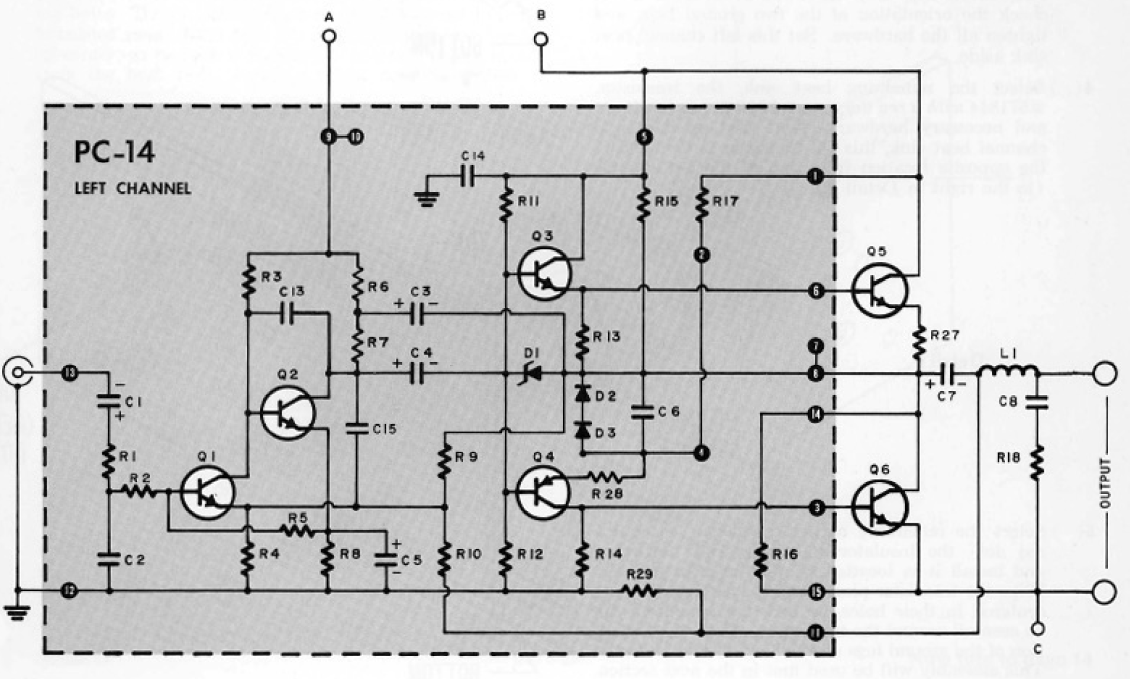
It had a fairly simple circuit with only 6 transistors per channel (see below), so it was really no more complex than a tube amp.
It had a more open and clean sound than my previous tube amps, (along with no hum) while using a lot less power.
I'm still using it today as the amp for my desk computer stereo system and it still sounds great.
The only thing I've every had to replace is one small electrolytic cap.

So the audio nuts with their "golden ears" can have their tube amps and scratchy vinyl records, but I'll never get close to either one again. :rolleyes:

stereo_120_later_schematic.png
 
Nice simple circuit.
There were some tube amps that had feedback taps on the o/p transformer and were classed as ultralinear, as some of the transformers shortcommings were canceled due to the feedback winding taps, however they are still no match signal integrity wise to a tranny, esp a fet.
Certain audiophites say valves sound 'warm', maybe due to the amount of soft clipping, I think the best place for a tube amp nowadays is guitarists, in the Uk the vox ac30 was and still is a classic, and it uses 4 El84's o/p tubes that were typically used in cheap radios at the time, and there was no feedback, some good guitarists would swap their granny for one.
 
There were some tube amps that had feedback taps on the o/p transformer and were classed as ultralinear, as some of the transformers shortcommings were canceled due to the feedback winding taps, however they are still no match signal integrity wise to a tranny, esp a fet.

Ultralinear wasn't about feedback taps from the transformer, as those were common place on HiFi valve amplifiers for many years - ultralinear referred to extra primary taps on the output transformer that the screen grids connected to, adding extra power input to the transformer.
 
Yes, that circuit is nice!
One I could happily build myself :)

It looks a bit 'weird', and looks like it has bad crossover distortion.

If you want to built a good quality simple old amp, google for the Leak Stereo 70 - nice simple circuit, using 2n3055's, a good 35W RMS (easily more than 50W), and a highly respected amp even today.
 
It looks a bit 'weird', and looks like it has bad crossover distortion.
It may look like it has crossover distortion to you but I can' hear any, even at low output levels.
Diodes D2 and D3 provide a small output bias current so it operates as an AB amp to minimize such distortion.
 
You can create a hybrid so that you don't need an output transformer.
Use transistors to buffer the output.

I have designed amplifiers with valve front end and with transistor output stages.
 
Welcome to ETO, nigel wright!

We've got two "nigel"s now :cool:. Are you in the UK, as well?
 
I can't see how D2 and D3 provide any bias?
That's true.
I was thinking the diodes were facing the other direction.

So basically the diodes are biased by R17 to balance the offset base-emitter voltages of Q4 and Q6 so the pair act as a PNP emitter follower with low offset, complementary to the NPN emitter follower (Darlington) pair of Q3 and Q5.
These four transistor are driven by the bootstrap output of Q2.

It may look like a weird circuit but it works well.
 
Status
Not open for further replies.

New Articles From Microcontroller Tips

Back
Top