Continue to Site

Welcome to our site!

Electro Tech is an online community (with over 170,000 members) who enjoy talking about and building electronic circuits, projects and gadgets. To participate you need to register. Registration is free. Click here to register now.

  • Welcome to our site! Electro Tech is an online community (with over 170,000 members) who enjoy talking about and building electronic circuits, projects and gadgets. To participate you need to register. Registration is free. Click here to register now.

Source impedance

Status
Not open for further replies.

atferrari

Well-Known Member
Most Helpful Member
I am trying to grasp properly the concepts of output impedance and input impedance.
/edit
Please, forget I mentioned input impedance.
/edit

Regarding the first (output impedance), I think I have a minimal idea but trying to calculate it in a real case, I fail miserably.

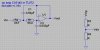
For the attached circuit I need to know the source impedance.

My questions:

a) Given the filter, what is the source impedance? Can you tell briefly how do you calculate (or just estimate) it?.

b) If I apply Vout (as Vsig) to the resistive divider, what is the source impedance at the output where I get Vdiv? Can you tell again, how do you calculate (or just estimate) it?

Gracias for any help on this.
 

Attachments

  • Source impedance.jpg
    Source impedance.jpg
    45.2 KB · Views: 168
Last edited:
You mention input and output impedance, so I'm not sure which you are referring to when you then ask about source impedance.

a) For the filter, the minimum input impedance is the value of R2 at high frequencies. It's frequency dependent due to C1 and and will increase as the frequency drops, reaching the value of the op amp input resistance at DC.

The filter output impedance is the closed-loop output impedance of the op amp. That's approximately the op amp open-loop resistance divided by the open-loop gain.

b) The output impedance of the voltage divider is simply the Thevenin equivalent of the two resistors. This is their parallel resistance or R3*R4/(R3+R4).
 
The filter is intended to be driven from a voltage source with ZERO output impedance. This so the INPUT impedance of the filter (complex number which changes at different frequencies) doesn't load the source.
 
Last edited:
Open loop resistance

Carl & Mike ML, thanks to you both for your time.

I edited somehow my OP to focus on the filter's output impedance.

Regarding the resistive divider, OK. Got it. No more problems with that.

But I still have to work out the source impedance of the filter. Open loop resistance? Have to understand that first.
 
I think you're confusing matters here by referring to "source impedance". What does that even mean?

Just use the simple, direct terms, input impedance and output impedance, as seen from the point of view of the circuit (filter). That way everyone knows what everyone else is talking about.
 
But I still have to work out the source impedance of the filter. Open loop resistance? Have to understand that first.
The op amp open loop resistance (output resistance) is normally given in the device's data sheet as is the open loop gain (which varies with frequency therefore so does the closed-loop output impedance).
 
What could I say?

Hola zit,

After reading, amongst others, this paragraph in the datasheet of the 18F452 that says:

"The source impedance affects the offset voltage
at the analog input (due to pin leakage current)."

and finding several topics in the NI site like this:

Source Impedance - NI Digital Waveform Generator/Analyzer Help - National Instruments

I finally, like an educated pupil, prior coming here, and just in case, did a Google search (what else?) and got this in the very first paragraph: (bolds as you can read it there)

The output impedance, source impedance, or internal impedance of an electronic device is the opposition exhibited by its output terminals to the flow of an alternating current (AC) of a particular frequency as a result of resistance, inductance and capacitance. It is the Thévenin equivalent impedance looking back into the output terminals.

What could I say?
 
Last edited:
The common usage of source impedance refers to the output impedance of the signal source driving the circuit you are concerned about (the filter, in this case).

If you will reread my post in this context, you will see that is what I was talking about.
 
Last edited:
Status
Not open for further replies.

Latest threads

New Articles From Microcontroller Tips

Back
Top