Continue to Site

Welcome to our site!

Electro Tech is an online community (with over 170,000 members) who enjoy talking about and building electronic circuits, projects and gadgets. To participate you need to register. Registration is free. Click here to register now.

  • Welcome to our site! Electro Tech is an online community (with over 170,000 members) who enjoy talking about and building electronic circuits, projects and gadgets. To participate you need to register. Registration is free. Click here to register now.

Start/Stop Setup...What am I missing

Status
Not open for further replies.

Mishael

Member
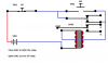
Hi all, simply put I have a start/stop momentary button assembly that I want to wire to a relay but I'm not sure what kind of relay to obtain. The start button is NO and the stop button is NC, I want a relay that will LATCH on the start PULSE, then unlatch when you press stop. I have seen this exact setup done but with a time delay relay and I do not want that because one, I don't want time... and two, the relay in question is $75 and thats just too expensive.

What kind of relay am I looking for? Its not a straight latching, and its not a straight impulse, but its not a flip-flop either. Its like a combination of all of them and I do not know what it is called...
 
Use a standard relay and use one of the NO
contact of the relay to latch it thru the NC contact of the stop button.
If the stop button has two NC contacts, also use one to feed
the start button as well so that if both are pushed, the stop
Button will override the start button.
 
The buttons are both momentary so it has to be a pulsed input and both buttons are single pole, they have no extra contacts
 
There is no schematic, they are simply two modular momentary contacts with a start/stop button head
I will get a part number when I am home
 
There is no schematic, they are simply two modular momentary contacts with a start/stop button head
I will get a part number when I am home

So...I want to be sure i understand when you say "Pulse" . If you continuously hold the start button pressed, does the output voltage stay "on". Or does it rise and fall between no volts and, say, 12 volts?
It sound like you mean it's either "on steady" when pressed or "off" when released.
 
Try this circuit....per post #2.

Ken
 

Attachments

  • StartStopRelay.gif
    StartStopRelay.gif
    3.6 KB · Views: 187
Maybe this would kind of show you how to do what you want
 

Attachments

  • latching relay.png
    latching relay.png
    12.7 KB · Views: 173
Last edited:
That's not going to latch
Not true. Depending on the supply voltage, the relay's dropout voltage, the relay coil current, and the resistor's value...it will pull-in when the NO switch is closed... and it will latch at a lower current when the switch is released.

Ken
 
Hi

Ken is correct and described circuit operation perfectly.

The resistor is optional and is used to reduce power consumption while the relay is latched.

eT
 
LOL Ken's is the same as mine he just added a EMF diode and a current limiting resistor and I didn't see the tie to the coil when I first looked at it.
 
Counter EMF diode is only really needed if a switching component like transistor needs protection.

Ken
 
That's a point, as the button and relay contacts won't be destroyed by the high voltage back EMF pulse.

But personally I would still keep the diode as it should reduce the NC button arcing on coil turnoff, to increase the life of the button contacts. :)
 
Wait guys
Most START/STOP stations are designed for use with contactors with AUXILLARY CONTACTS. This is discussed here: https://www.google.com/url?sa=t&rct...lQSyBMHOFNLKsHw&bvm=bv.49784469,d.dmg&cad=rja

A contactor for 240 V would have two poles for the 240 and a small pilot rated contact as the AUX contact. That AUX contact is closed when the relay is closed. That contact is wired in parallel to the momentary START switch. Thus once presses the start switch is continuously on until you loose power.
Now, if you wire that parallel combination to a power source and the relay coil, you can turn it on, but ont off. Insert a NC PB in series with the relay coil and presto: ON/OFF Start Stop control with drop on power failure.

Overloads complicate the wiring a bit, but not much,

Most of the motor starters I wired had a switch for.
OFF/ON/(Start/Stop)
so they could function as always on, always off or use the start stop buttons.
They were all fitted with a solid state motor starter later.
Earlier, I used a phase reversal relay with delays for autostart and phase problems.

Agreed, this was costly, but not as costly as loosing the pump or the process. It was used to protect a compressor in a 40K USD unit and pumps that cost $5K with considerable repair downtime.
 
That's nice info I really don't know why i wasted time drawing out a circuit. But what I drawled is a easy way to use a dpdt relay and two switches NO and NC to latch a relay on to control a higher voltage load.
And was for single phase AC power. Used in motor starters in shop tools. But Its just a simple example.
 
Status
Not open for further replies.

Latest threads

Back
Top