JASSMITHUS
New Member
A PCB board circuit that controls a Door Drive Motor in an Elevator for opening/closing the sliding doors (machine room less elevator) currently runs on a Single Phase Supply of about 230 V (Input Range: 100 V - 230 V +10% -15%). The PCB board is connected via cables to the PM motor which runs on 3 phase supply, and an Encorder as well. *Assuming the single phase gets converted to 3 phase within the PCB board.
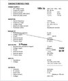
The main PCB board specs are:
LIN / LOUT: 0.55A/0.85A
PIN/POUT: 126 / 100 W
The PM Motor specs are: 106 V / 94 W / 1.22 A
Problem: The PCB board circuit gets damaged when power supply surge occurs. Even though the PCB circuit has 2 ceramic fuses of 4A each, still the Varistor or other electronic components on the PCB including a microcontroller get damaged. The manufacturing company staff recommends running the PCB Board via a STEP DOWN TRANSFORMER of 230 V to 180 V at 300 VA. Since 180 v is a non standard output voltage, a made to order step down transformer is needed. However the ratings for the transformer are not very clear to me. The lift technician whom I contacted, suggested a 500VA step down transformer instead of a 300 VA. This was costlier as well. However there seems to be some serious questions on the output CURRENT. i.e. How much is required based on the equipment tags/specs and will a step down transformer increase the CURRENT and if so what is the solution, so that the PCB board does not get damaged due to high current/heat? Currently Voltage Stabilizers that are used for home electronics like LCD TVs are not suggested.
Formula POWER = VOLTAGE x CURRENT. I am assuming the below is some where near the truth.
300 VA transformer => at 180 V Secondary would have CURRENT as 300/180= 1.66 A
500 VA transformer => at 180 V Secondary would have CURRENT as 500/180 = 2.78 A
What should be Step Down Transformer Specs based on the equipment tags / ratings given above? 300VA or 500 VA and should output CURRENT also be specified?
Attaching the Power Supply section from an older manual for the door drive as well. Asking for use in India, where supply is usually 230V.