Continue to Site

Welcome to our site!

Electro Tech is an online community (with over 170,000 members) who enjoy talking about and building electronic circuits, projects and gadgets. To participate you need to register. Registration is free. Click here to register now.

  • Welcome to our site! Electro Tech is an online community (with over 170,000 members) who enjoy talking about and building electronic circuits, projects and gadgets. To participate you need to register. Registration is free. Click here to register now.

stepper motor wires

Status
Not open for further replies.

ProFPGA

Banned
hi ,

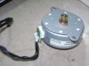
I have to use this stepper motor part no:pM55L-048 .
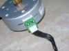
All of its wires are black and i am without a clue which one is which .
I would be gratful if someone has the same motor with colour code and give the correct info on the control wires.

i am attaching pics of this motor .
 

Attachments

  • stepprmtr..JPG
    stepprmtr..JPG
    1.2 MB · Views: 367
  • steppmtr1..JPG
    steppmtr1..JPG
    1.1 MB · Views: 321
You can't tell only from the picture. However, one of the wire shall measure half as much resistance between itsef and each of the other wires compared to the other pairs. This wire would be connected to center point.
Apart from that, the other wires is usually mountet (in respect to the flat cable) in an rotation order.
 
i did measured the impedence with the middle wire and yes its even from that connection to either side.
but still want to know which one is which .
 
i did measured the impedence with the middle wire and yes its even from that connection to either side.
but still want to know which one is which .
With steppers it's not important. Just connect it and have fun :D
 
Test it by connecting the common on one of the terminals. Then alternate the supply on the other terminals. the right combination will get the motor turning in steps, completing its revolution with a few alternates, so to say.
 
I have been using that exact stepper motor, you pulled it from a printer right? the wire pulses go in order from one end of the line of wires to the other, the direction of course depends on which direction you want to turn, and the middle is the center lead. I set mine up with a ULN2803 darlington array IC, but there are lots of darlington arrays that will do. Its simple wiring cause all the inputs on most darlington arrays are straight across from the ports they controll, and the power for the chip is the two pins at the end farthest from the notch. All you have to do is power it accordingly, plug the outputs to your motor, the corresponding inputs to your MCU or parallel port, and pulse the inputs in order.
 
Last edited:
hi , yes i did pulled it out of an old printer .
i would appreciate if you could tell me which one is A1, A2, A3, B1, B2 & B3.
i understand that A2 and B2 are center tapped in UNI-polar mode.
and i presume there is common +ve as well .
if you could tell me especially from looking at the 2nd pic ?
please find attached its datasheet from the manufacturer.

thanks
 

Attachments

  • PM55L_stpr_mtr..pdf
    761.3 KB · Views: 585
Last edited:
I'm not exactly sure which wires have which lables. I would guess that the first wire on the left is A1, then going toward the right A3, A2/B2, B1, B3.
 
There isnt a lot of damage you can do, since the resistance between the wrong wires is actually greater than that between the right wires. Infact what youre suggesting is a good way to make sure you have it right, connect the middle wire to the positive terminal of a 6-12 volt power supply or battery, and when you touch one of the other wires to the negative terminal, the motor will jump to the position that wire goes with, do them in order and it will make tiney equal sized jumps in the same direction, and at the end if you do the first one again it will make another jump in the same direction it did before.
 
hi , i tried to run it in bi-polar via directly pic18f4523. with diode in series just in case there is back emf .
but it dosent buj, may be the output pulses are 5.0v .
did you drived it with 6v and above ??
it does lights up a led , but the motor doesnt move.
i wanted to use uln2803 , but it inverts the outputs .
 
That's perfect for your bipolar stepper.

Connect the center taps of the coils to the positive rail of your supply and have the outer taps controlled by pulling them to ground using an ULN.
 
ok , i have outputs from pic going into 1b,2b, 3b & 4b of ULN2803.
i had 9v battry with gnd connected to uln gnd and com conncted to +9v.
i had A3/B3 of motor connected to gnd and then to +ve supply for testing.
and A1, B1, A2 and B2 to respective o/p of uln
the motor didnt move .
the led's are lighting as expected.

am i missed something here ????
 
Did you connect the ground from your microcontroller powersupply to the ground (-) of your 9v battery?
 
That's perfect for your bipolar stepper.

Connect the center taps of the coils to the positive rail of your supply and have the outer taps controlled by pulling them to ground using an ULN.

A 6 wire (or even 5wire) that is using the center taps is a UNIPOLAR stepper motor. Bipolar only uses A1-A2 and B1-B2.

See the Jones on stepper link I posted a couple of days ago.
 
A 6 wire (or even 5wire) that is using the center taps is a UNIPOLAR stepper motor. Bipolar only uses A1-A2 and B1-B2.

See the Jones on stepper link I posted a couple of days ago.

Sorry, that happened the second time. :)

I always mix up unipolar and bipolar.

Of course I meant unipolar.

Talking about stepper motors in the future just remember to think "unipolar" when I say "bipolar". :D
 
yes , you are right its a five wire connector on the motor.
So the center connection is the com and it is to be conncted to +ve supply.
so its got to be a UNIPOLAR , now i will have to change my firmware .
My be this is the real problem .
 
Status
Not open for further replies.

New Articles From Microcontroller Tips

Back
Top