Continue to Site

Welcome to our site!

Electro Tech is an online community (with over 170,000 members) who enjoy talking about and building electronic circuits, projects and gadgets. To participate you need to register. Registration is free. Click here to register now.

  • Welcome to our site! Electro Tech is an online community (with over 170,000 members) who enjoy talking about and building electronic circuits, projects and gadgets. To participate you need to register. Registration is free. Click here to register now.

Stereo to mono class-d amplifier

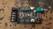
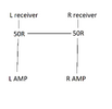
Amp will be used for videogames, connected through 3.5mm to monitor. I am trying to convert stereo amp into mono but keep the volume knob. pins going in and out of the potenciometer are marked yellow, where i want to join L and R with resistor is marked red. So i am wondering, instead of putting separate resistor on each channel, could i just use 1 to bridge L and R channel (marked with red R) ? It wont be perfect mono, but for video games .., and i at least i protect the channels a bit and get to keep the potenciometer. The potenciometer when turned all the way has 1.2 ohm.

edit: Amp will be connected only through 3.5mm jack, so bluetooth wont be used. Would it be easier to just make mono using the pins around 3.5" ? Desolder the pins and put 50 or 100 ohms on each channel ?
 

Attachments

  • 20240626_180430 - Copy.jpg
    20240626_180430 - Copy.jpg
    3.2 MB · Views: 26
  • 20240626_180430.jpg
    20240626_180430.jpg
    3.8 MB · Views: 24
  • 20240626_180454.jpg
    20240626_180454.jpg
    3.6 MB · Views: 23
Just join left and right on the 3.5mm socket pins - it's so simple as not to need asking.
But then why was i instructed to put resistor on each channel in the other thread when it was about bluetooth amplifier ? Was it to protect the bluetooth receiver and it doesn't apply now since i am using 3.5mm instead of bluetooth, and using 3.5mm turns off the bluetooth receiver anyway ? See scheme
 

Attachments

  • scheme.png
    scheme.png
    24.9 KB · Views: 13
But then why was i instructed to put resistor on each channel in the other thread when it was about bluetooth amplifier ? Was it to protect the bluetooth receiver and it doesn't apply now since i am using 3.5mm instead of bluetooth, and using 3.5mm turns off the bluetooth receiver anyway ? See scheme

A small number of people here seem to repeatedly make such a suggestion - based on the HIGHLY unlikely idea that the source has zero output impedance, or has a standing DC voltage on it, both of which are extremely unlikely.

If you want, add resistors - it's just a waste of time and two resistors.
 
If you don't know the details of the output circuit supplying the audio signals, a series resistor in each channel is the prudent thing to do. As a guess, something in the 100 ohm to 1 K range. Lower than that and you might overload the output circuit. Higher than that, the signal might be attenuated a noticeable amount.

OTOH, Nigel has done a whole butt-load more consumer electronics than I have.

ak
 
If you don't know the details of the circuit supplying the audio signal, a series resistor in each channel is the prudent thing to do. As a guess, something in the 100 ohm to 1 K range. Lower than that and you might overload the output circuit. Higher than that the signal might be attenuated a noticeable amount.

ak

Exactly as I said :D - paranoia :D
 
Thank you ! That is indeed good news. But now i am just paranoid enough that i cant decide what to do. Maybe i can do what i do when im unsure - just add a resistor of such a low value that it wont do any good, but will sure make me feel better. Something like 10 ohms between channels xD Usualy i added something like 30 ohms. When i tried 100 ohms i could certanly hear the difference, i am very sensitive to it, even if its just a few % SPL

Just out of curiosity and to learn something new. Is the theory behind adding a resistor the fear that when 1 channel is playing nothing and 1 channel is blasting at 100%, the signal will go from 1 channel to the other on the receiver and damage it, instead of going towards the amplifier ?
 
The imaginary 'fear' is that you're shorting one low impedance output to another, so if you directly couple the VERY low impedance outputs (probably much lower than 0.1 ohms?) of a stereo amplifier together, one output could go high, while the other goes low, and cause a huge amount of current to flow.

In practice, you wouldn't join the outputs of a stereo amplifier (unless you also joined the inputs). Headphone outputs, preamp outputs, bluetooth outputs, etc. are relatively high impedance, so you can join them with no issues.

But feel free to add resistors if you wish (they are your resistors to waste), if it's lowering the volume slightly, just turn it up - how would you possibly know it was quieter anyway?.
 
Usualy when i make a speaker it's to be portable and it's for someone young whos listening to new trashy music and just wants max bass and SPL. Usualy they listen to it turned up so high that its a distorted mess but as long as it's louder than their friends speaker, they are happy.

Yeah, it shouldn't be a problem with this amp. I measured the resistance and even with potenciometer turned all the way to the max, i still measure 1.5 ohms, while my multimeter has 0.3 ohms, meaning there is 1.2 ohms in the potenciometer.

Could i maybe ask another question without opening a new topic ?

I have this very same amp connected through 3.5mm to audio output from my usb DAC, which is connected to my computer. Now, this 3.5mm jack on amplifier i am guessing is made to be connected with something weak like a mobile phone. I don't know if signal coming from my DAC is that much stronger. But using 4 ohm speakers connected to this amp, the sound is unbelivably loud. So loud that i never turned it up more than 30% and i also added 8 ohm resistor in series with each speaker. The problem is that because of that i can only use about 30% of the full potenciometer's range and it makes fine tuning the loudness very hard. So i am wondering if i could lower the loudness by putting a resistor on each channel of the 3.5mm jack. Meaning i would desolder the 3.5mm jack legs at L and R channel and put a resistor there. I would pick the value of the resistor such that loudness i now hear at 30% would then be heard at 60%.
 
Usualy when i make a speaker it's to be portable and it's for someone young whos listening to new trashy music and just wants max bass and SPL. Usualy they listen to it turned up so high that its a distorted mess but as long as it's louder than their friends speaker, they are happy.

Yeah, it shouldn't be a problem with this amp. I measured the resistance and even with potenciometer turned all the way to the max, i still measure 1.5 ohms, while my multimeter has 0.3 ohms, meaning there is 1.2 ohms in the potenciometer.

None of that makes any sense?, whatever you're measuring you're measuring it wrongly, and in the wrong place.

Could i maybe ask another question without opening a new topic ?

I have this very same amp connected through 3.5mm to audio output from my usb DAC, which is connected to my computer. Now, this 3.5mm jack on amplifier i am guessing is made to be connected with something weak like a mobile phone. I don't know if signal coming from my DAC is that much stronger. But using 4 ohm speakers connected to this amp, the sound is unbelivably loud. So loud that i never turned it up more than 30% and i also added 8 ohm resistor in series with each speaker. The problem is that because of that i can only use about 30% of the full potenciometer's range and it makes fine tuning the loudness very hard. So i am wondering if i could lower the loudness by putting a resistor on each channel of the 3.5mm jack. Meaning i would desolder the 3.5mm jack legs at L and R channel and put a resistor there. I would pick the value of the resistor such that loudness i now hear at 30% would then be heard at 60%.

A phone is designed to drive headphones, and following the modern requirement not to damage idiots hearing (apparently modern kids are too thick to be able to control their own volume?) have severely restricted output levels. Funnily enough I've been testing a 1000W+1000W RMS PA amp earlier today that we're building for a forthcoming gig (to feed sub-woofers). To test it I fed it from a CD Walkman - and because my scope was next to it I stuck it on the output, the Walkman output was peaking at only about 100mV p-p.

In your case, feeding an amp from a proper line output, it would be perfectly normal to add resistors in the top end of the volume control.
 
First, your question about combining left and right.
Since the amplifier of each channel of your source audio likely has some feedback circuitry to control output, you need at least as much resistance as your amplifier was designed to drive if you are supplying from your speaker wires - otherwise you'll have a dead short to two different voltage levels when the two channels are not playing the exact same audio.

If you are supplying line voltage, add a. 100 to 4,7k in series with each + output. Since most of these class D amplifiers are using JFET inputs, the current limiting of the resistor is not changing anything since no current flows into the gate of the jfet (input of the op amp). Add the resistors - it's not a waste of time if your source music is truly stereo.

Next, regarding your excessive volume,
your board says input voltage can be 5-27v (if I can read that correctly, if you don't want the high end of volume, use a lower voltage power supply. 9 to 12v is plenty in most cases.
 
Since the amplifier of each channel of your source audio likely has some feedback circuitry to control output
That's my reasoning for always using some lowish value resistors to combine two channels - nothing to do with overloading or damaging anything, when working with low levels signals, but due to the probability of increased distortion by messing up the two individual output amps feedback.
 
That's my reasoning for always using some lowish value resistors to combine two channels - nothing to do with overloading or damaging anything, when working with low levels signals, but due to the probability of increased distortion by messing up the two individual output amps feedback.

Which is already included in any even slightly competently designed line output used to feed his power amplifier.
 
That's my reasoning for always using some lowish value resistors to combine two channels - nothing to do with overloading or damaging anything, when working with low levels signals, but due to the probability of increased distortion by messing up the two individual output amps feedback.
And, since we don't know how these $40 Bluetooth + class D amplifier boards are well designed by famous electronics companies that want to uphold their reputation like " " (no name on the circuitboard), I'm sure they add a bunch of protection circuitry to their designs. I'm sure the $20 including shipping has more than enough margin to cover the extra board space and components.
 
Which is already included in any even slightly competently designed line output

But who is using that type of gear?

Most small devices such as phones and audio players - and many audio "gadget" modules - have headphone-compatible amplifiers for the audio output sockets or connectors.

Those are intended to drive relatively low impedances; they are not "Line level" audio on HiFi separates or professional gear.


And note the common "JL" bluetooth ICs such as in these do specifically have headphone amps for the outputs!

eg.

Common 24 pin JL Bluetooth IC datasheet, via a link on eevblog:

From that, a direct headphone driving application should have ten ohm series resistors in the outputs - but do the module makers bother? Not the ebay one that I can see, and I doubt it very much when they are connecting to a volume pot on an amp module!


A couple of resistors as a stereo combiner do no harm but do reduce the possibility of introducing (easily avoidable) distortion.
 
But who is using that type of gear?

Most small devices such as phones and audio players - and many audio "gadget" modules - have headphone-compatible amplifiers for the audio output sockets or connectors.

Those are intended to drive relatively low impedances; they are not "Line level" audio on HiFi separates or professional gear.

No, they are designed for the outputs to be shorted together if required, and headphone outputs are particularly high impedance (due to the 'nanny' state) to make them dead quiet. As I mentioned above, my CD Walkman only outputs 100mV p-p.
 

Latest threads

Back
Top